
User's Manual
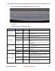
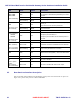
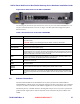
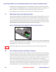
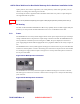

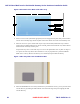
Table Of Contents
- Chapter 1 Introduction
- Chapter 2 Overview
- 2.1 Overview of ONT-2-E4xxxi Multi-service Residential Gateway Series
- 2.2 EPON Multi-service Gateway Series Hardware Interface
- 2.3 Supported Residential Gateway (RG) Features
- 2.3.1 Network Address Translation (NAT)/NAPT (Network Address Port Translations)
- 2.3.2 Dynamic Domain Name System (DDNS)
- 2.3.3 Dynamic Host Configuration Protocol (DHCP) Client and Server
- 2.3.4 Security Firewall and Rich Packet Filtering
- 2.3.5 Advanced Quality of Service,
- 2.3.6 Virtual Server
- 2.3.7 Flexible Management Interfaces including Web GUI
- 2.4 Additional Features
- 2.5 Product Specifications
- 2.6 Physical Characteristics
- Chapter 3 Hardware Description
- 3.1 Package Contents
- 3.2 Accessories
- 3.3 ONT-2-E4xxxi Multi-service Residential Gateway Series Enclosure
- 3.4 LED Diagnostics on Front Panel
- 3.5 Rear Panel and Interface Description
- 3.6 Ethernet Connections
- 3.7 EPON SC/APC Fiber Optic Network Interface
- 3.8 Voice Telephony Interfaces (Standard Telephone)
- 3.9 RF Overlay
- 3.10 Power
- Chapter 4 Installing the ONT-2-E4xxxi Multi-service Residential Gateway Series
- 4.1 Cautions and Warnings
- 4.2 Pre-Installation Check
- 4.3 Tools and Materials Needed
- 4.4 System Requirements
- 4.5 Situating the EPON Multi-service Gateway ONT
- 4.6 Wall-Mounting the ONT Using the Fiber Tray
- 4.7 Wall-Mounting the ONT without the Fiber Tray
- 4.8 Vertical or Tower Mounting the ONT
- 4.9 Connecting the EPON Optical Fiber to the ONT
- 4.10 Connecting Telephones to the EPON Multi-service Gateway ONT
- 4.11 Connecting Premises LAN Ethernet Wiring
- 4.12 Connecting Power and Powering Up the ONT
- 4.13 Connecting to the GUI Interface of the ONT
- Index

ONT-2-E4xxxi Multi-service Residential Gateway Series Hardware Installation Guide
24 UNRELEASED DRAFT TM 87-10879 Rev. A
Figure 6 Schematic of the Back of the Fiber Tray
4. Select 2 screws or nails (with heads appropriately sized to snugly fit the keyhole slots), and insert them
into the wall so that they align with the keyhole slots. Ensure that the screw/nails are horizontally level.
5. When the screws are in place and the fiber tray is ready to be mounted, hold the fiber tray so that its
keyhole slots are positioned directly over the screw heads, push it back towards the wall, and then slide it
downward until it is firmly seated in place.
Snap the fiber tray cover over the fiber tray. You can wire the optical fiber cable any time. See Figure 7
for a picture of a fiber tray that has been mounted on a wall, in preparation for a provisioned EPON
Multi-service Gateway. Remove the fiber tray cover and deftly snap the ONT onto the tray.
Figure 7 Fiber Tray with Cover Installed on Wall
6. When the EPON Multi-service Gateway ONT has been provisioned for service, you can place the ONT
onto the fiber tray by holding the ONT with the Aurora Networks logo on top and snapping the ONT
onto the fiber tray.