
User's Manual

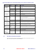
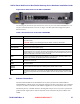
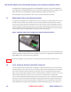


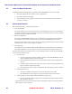


Table Of Contents
- Chapter 1 Introduction
- Chapter 2 Overview
- 2.1 Overview of ONT-2-E4xxxi Multi-service Residential Gateway Series
- 2.2 EPON Multi-service Gateway Series Hardware Interface
- 2.3 Supported Residential Gateway (RG) Features
- 2.3.1 Network Address Translation (NAT)/NAPT (Network Address Port Translations)
- 2.3.2 Dynamic Domain Name System (DDNS)
- 2.3.3 Dynamic Host Configuration Protocol (DHCP) Client and Server
- 2.3.4 Security Firewall and Rich Packet Filtering
- 2.3.5 Advanced Quality of Service,
- 2.3.6 Virtual Server
- 2.3.7 Flexible Management Interfaces including Web GUI
- 2.4 Additional Features
- 2.5 Product Specifications
- 2.6 Physical Characteristics
- Chapter 3 Hardware Description
- 3.1 Package Contents
- 3.2 Accessories
- 3.3 ONT-2-E4xxxi Multi-service Residential Gateway Series Enclosure
- 3.4 LED Diagnostics on Front Panel
- 3.5 Rear Panel and Interface Description
- 3.6 Ethernet Connections
- 3.7 EPON SC/APC Fiber Optic Network Interface
- 3.8 Voice Telephony Interfaces (Standard Telephone)
- 3.9 RF Overlay
- 3.10 Power
- Chapter 4 Installing the ONT-2-E4xxxi Multi-service Residential Gateway Series
- 4.1 Cautions and Warnings
- 4.2 Pre-Installation Check
- 4.3 Tools and Materials Needed
- 4.4 System Requirements
- 4.5 Situating the EPON Multi-service Gateway ONT
- 4.6 Wall-Mounting the ONT Using the Fiber Tray
- 4.7 Wall-Mounting the ONT without the Fiber Tray
- 4.8 Vertical or Tower Mounting the ONT
- 4.9 Connecting the EPON Optical Fiber to the ONT
- 4.10 Connecting Telephones to the EPON Multi-service Gateway ONT
- 4.11 Connecting Premises LAN Ethernet Wiring
- 4.12 Connecting Power and Powering Up the ONT
- 4.13 Connecting to the GUI Interface of the ONT
- Index

ONT-2-E4xxxi Multi-service Residential Gateway Series Hardware Installation Guide
TM 87-10879 Rev. A UNRELEASED DRAFT 17
Figure 2 Rear Panel Ports on the ONT-2-E4020iWn
The following table describes the ports and interfaces on the rear panel of the ONT-2-E4020iWn. For a de-
scription of the PON optical fiber connector, see Figure 3 SC/APC Optical Fiber Plugged into Optical
Network Interface.
Table 7 Rear Panel Ports on the ONT-2-E4020iWn
Interface
Description
ON/OFF
Power ON/OFF switch. Depress button to turn on. Power off the device when it is not in use,
for power saving.
CAUTION: Beware of accidentally pressing this button—it will turn off the ONT.
Power
Connect to the supplied power adapter.
Backup Power
Connect to an external power supply.
Reset
Restore to factory defaults. If you power on the device and use a thin needle to press the
Reset button for over 1 second, the ONT is automatically reset and is restored to the factory
default settings.
If you cannot log in to the ONT or forget your username/password, press this
button for more than 6 seconds to restore to defaults.
WPS
Press to activate Wi-Fi Protected Setup (WPS) for a period of time. Activating WPS in this
manner may override your disabling WPS via the GUI interface.
WiFi
Reserved for future use.
LAN1, LAN2, LAN3,
LAN4
RJ-45 Ethernet interface with the self-adaptive rate of 10/100/1000 Mbps, for connecting to
the local network.
Phone1
Phone2
Connect these two voice ports to an analog phone set with a RJ-11 cable.
USB
Reserved for future use. In the future, the standard USB connector will accommodate back
up of local configuration data and firmware updates via mass storage media, such as a flash
drive.
3.6 Ethernet Connections
The ONT-2-E4xxxi Multi-service Residential Gateway Series provides four switched Ethernet
10/100/1000 Base-T RJ-45 copper wire twisted pair interfaces for direct connection to a PC or Ethernet
set top box, or indirect connection to other Ethernet equipment via an attached switch, hub, or router.
All Ethernet ports are “switched” interfaces, meaning that each port can act as part of a separate inde-
pendent network segment, hence video or data traffic can be restricted to the port for which it is in-
tended.