
User's Manual
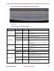
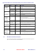
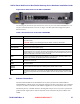
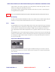

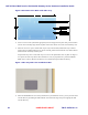
Table Of Contents
- Chapter 1 Introduction
- Chapter 2 Overview
- 2.1 Overview of ONT-2-E4xxxi Multi-service Residential Gateway Series
- 2.2 EPON Multi-service Gateway Series Hardware Interface
- 2.3 Supported Residential Gateway (RG) Features
- 2.3.1 Network Address Translation (NAT)/NAPT (Network Address Port Translations)
- 2.3.2 Dynamic Domain Name System (DDNS)
- 2.3.3 Dynamic Host Configuration Protocol (DHCP) Client and Server
- 2.3.4 Security Firewall and Rich Packet Filtering
- 2.3.5 Advanced Quality of Service,
- 2.3.6 Virtual Server
- 2.3.7 Flexible Management Interfaces including Web GUI
- 2.4 Additional Features
- 2.5 Product Specifications
- 2.6 Physical Characteristics
- Chapter 3 Hardware Description
- 3.1 Package Contents
- 3.2 Accessories
- 3.3 ONT-2-E4xxxi Multi-service Residential Gateway Series Enclosure
- 3.4 LED Diagnostics on Front Panel
- 3.5 Rear Panel and Interface Description
- 3.6 Ethernet Connections
- 3.7 EPON SC/APC Fiber Optic Network Interface
- 3.8 Voice Telephony Interfaces (Standard Telephone)
- 3.9 RF Overlay
- 3.10 Power
- Chapter 4 Installing the ONT-2-E4xxxi Multi-service Residential Gateway Series
- 4.1 Cautions and Warnings
- 4.2 Pre-Installation Check
- 4.3 Tools and Materials Needed
- 4.4 System Requirements
- 4.5 Situating the EPON Multi-service Gateway ONT
- 4.6 Wall-Mounting the ONT Using the Fiber Tray
- 4.7 Wall-Mounting the ONT without the Fiber Tray
- 4.8 Vertical or Tower Mounting the ONT
- 4.9 Connecting the EPON Optical Fiber to the ONT
- 4.10 Connecting Telephones to the EPON Multi-service Gateway ONT
- 4.11 Connecting Premises LAN Ethernet Wiring
- 4.12 Connecting Power and Powering Up the ONT
- 4.13 Connecting to the GUI Interface of the ONT
- Index

ONT-2-E4xxxi Multi-service Residential Gateway Series Hardware Installation Guide
TM 87-10879 Rev. A UNRELEASED DRAFT 15
Figure 1 LED Indicators on EPON Multi-service Gateway ONT
See Table 6 for a description of the LED indicators located on the front top of an EPON Multi-service
Gateway ONT.
Table 6 LED Indicators and Descriptions
LED
Color
Status
Description
PWR (Power) or
SYS (System)
Green-Blinking Blinks Booting up.
Green-Solid On ONT is operating.
Backup Power
Dark Off No backup power is present.
Green-Solid On Backup power is present.
Green-Blinking On
Slow blinking green when ONT is running on backup
power.
Fast blinking green when a problem exists with the
backup power.
EPON
Dark On
No fiber uplink to EPON interface or failed to connect
over EPON network.
Green-solid On
PON uplink is OK, and EPON network connection is
operational.
Alarm
Dark Off No alarm condition exists.
Red-Blinking Blinks Alarm condition exists.
WAN (Internet)
Dark Off
No fiber uplink to EPON interface or ONT model is
configured by Service Provider so that it does not have
a routed connection to the internet.
Green-Blinking Slow Blink
During DHCP, ONT failed to receive an IP address
from the service provider.
Green-solid On ONT is connected to the WAN.