
User's Manual


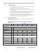
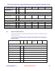

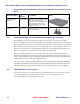
Table Of Contents
- Chapter 1 Introduction
- Chapter 2 Overview
- 2.1 Overview of ONT-2-E4xxxi Multi-service Residential Gateway Series
- 2.2 EPON Multi-service Gateway Series Hardware Interface
- 2.3 Supported Residential Gateway (RG) Features
- 2.3.1 Network Address Translation (NAT)/NAPT (Network Address Port Translations)
- 2.3.2 Dynamic Domain Name System (DDNS)
- 2.3.3 Dynamic Host Configuration Protocol (DHCP) Client and Server
- 2.3.4 Security Firewall and Rich Packet Filtering
- 2.3.5 Advanced Quality of Service,
- 2.3.6 Virtual Server
- 2.3.7 Flexible Management Interfaces including Web GUI
- 2.4 Additional Features
- 2.5 Product Specifications
- 2.6 Physical Characteristics
- Chapter 3 Hardware Description
- 3.1 Package Contents
- 3.2 Accessories
- 3.3 ONT-2-E4xxxi Multi-service Residential Gateway Series Enclosure
- 3.4 LED Diagnostics on Front Panel
- 3.5 Rear Panel and Interface Description
- 3.6 Ethernet Connections
- 3.7 EPON SC/APC Fiber Optic Network Interface
- 3.8 Voice Telephony Interfaces (Standard Telephone)
- 3.9 RF Overlay
- 3.10 Power
- Chapter 4 Installing the ONT-2-E4xxxi Multi-service Residential Gateway Series
- 4.1 Cautions and Warnings
- 4.2 Pre-Installation Check
- 4.3 Tools and Materials Needed
- 4.4 System Requirements
- 4.5 Situating the EPON Multi-service Gateway ONT
- 4.6 Wall-Mounting the ONT Using the Fiber Tray
- 4.7 Wall-Mounting the ONT without the Fiber Tray
- 4.8 Vertical or Tower Mounting the ONT
- 4.9 Connecting the EPON Optical Fiber to the ONT
- 4.10 Connecting Telephones to the EPON Multi-service Gateway ONT
- 4.11 Connecting Premises LAN Ethernet Wiring
- 4.12 Connecting Power and Powering Up the ONT
- 4.13 Connecting to the GUI Interface of the ONT
- Index

ONT-2-E4xxxi Multi-service Residential Gateway Series Hardware Installation Guide
14 UNRELEASED DRAFT TM 87-10879 Rev. A
Table 5 Orderable Accessories for ONT-2-E4xxxi Multi-service Residential Gateway
Series
Accessory Name Part
Number
Description Image
Fiber storage tray
with cover
To be added.
The tray is used to store the optical
fiber cable. The tray can be
wall-mounted with the cable inside;
when the ONT has been provi-
sioned, the ONT can be quickly
snapped in the tray.
Tower stand To be added.
The tower stand is used for vertical
or tower mounting.
3.3 ONT-2-E4xxxi Multi-service Residential Gateway Series Enclosure
The EPON Multi-service Gateway ONTs are similar across the series. The ONT-2-E4xxxi Mul-
ti-service Residential Gateway Series is designed for inside building customer premises and/or inside
plant environments. It can be placed on a desktop, or tower-mounted, or wall-mounted via keyhole slots
that are built into the bottom of the unit. It has an optional fiber tray for slack management of the video
fiber cable. Once the fiber tray is wall-mounted, the ONT can be easily and quickly snapped in any time.
It also has an optional tower bracket for tower-mounting (vertical mounting).
The front of the EPON Multi-service Gateway houses the system LED status indicators for Power,
Backup Power, EPON port, Alarm, WAN, four (4) LAN Gigabit Ethernet ports, two (2) telephone ports,
Voice over IP (VoIP) service, Wi-Fi, WPS, USB, and RF connectivity. Refer to
Figure 1 for the location
of LED indicators on an example ONT-2-E4020iWn unit.
Note that the ONT-2-E4000i and ONT-2-E4001i do not have telephone ports. The ONT-2-E4020iWn
and ONT-2-E4021iWn have wireless (Wi-Fi) access points that offer high speed wireless connectivity
with built-in antennas. Only the ONT-2-E4021i and ONT-2-E4021iWn have RF Overlay capability.
3.4 LED Diagnostics on Front Panel
The LED status indicators are on the top of the front of the EPON Multi-service Gateway ONT. The LEDs
can be used to diagnose the status of the ONT. See Figure 1 for a view of LED indicators on an
ONT-2-E4xxxi Multi-service Residential Gateway Series.