PRECISION AIR FEED ® INSTALLATION & OPERATING INSTRUCTION MANUAL
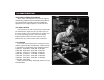
P/A INDUSTRIES INC. OVER FORTY YEARS EXPERIENCE Since 1954, P/A engineers have been designing and building equipment for the Metalforming Industry. Our commitment to provide innovative production equipment of the highest quality is second to none. CUP SEAL DESIGN P/A is the only air feed manufacturer that provides low maintenance, high-cycle life cup wiper seals on the main cylinder. Every quality-built air cylinder uses the same technology as P/A.
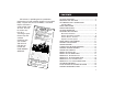
CONTENTS P/A believes in providing the best production performance air feed available anywhere in the world today. To prove that we are the BEST, a serialized Repair Certificate is enclosed with each air feed. This can be used at any time for a “no-charge” repair. Please keep this valuable Certificate with your records and return to P/A with the feed for our FREE REPAIR SERVICE. AIR FEED FEATURES .................................................... 2 MOUNTING THE AIR FEED ..................................
AIR FEED FEATURES FASTER SPEEDS Our patented system sequences high speed models up to 400 cycles per minute at full two inch pitch. VERSATILE Coil stock can be fed in any direction or angle at any time during the machine cycle. A single feed can push or pull through long or short progressions. A variety of stock widths and thicknesses can be fed at different speeds and feed lengths. Two or more strips can be simultaneously fed by the same feed.
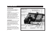
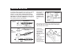
AIR FEED FEATURES Nylock hex nut used in aircraft engines to absorb vibration and eliminate loosening Shock absorber stops slamming and reduces noise Large adjusting screw and lock nut provide vernier feed length control Combination stock dampener and adjustable guide rollers provide vibration free material to the feed SIMPLE INSTALLATION Our feeds are extremely easy to mount. Two (or four) mounting bolts and a single air line connection are all that’s necessary.
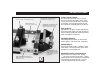
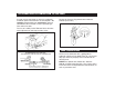
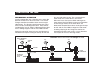
MOUNTING THE AIR FEED Its compact design will allow this Feed to be installed on the Die or Press Bolster, or on many types of machines, at any angle, including upside down or vertical. Use two (or four) minimal clearance HoldDown Bolts to solidly fasten the Feed as close to the Work Station as possible. NEVER use ‘C’ clamps as the Feed may move or shift position. Mounting directly on the Die is recommended for “Just-In-Time” production and to reduce set-up time.
AIR POWER SUPPLY CONNECTION TO THE FEED A single air line connection is all that is needed for maximum power with minimum air consumption. We strongly recommend that an oversized air hose be connected to the Feed with a water separator type filter and air line oiler. Set the Air Pressure Regulator between 80 and 120 PSI (6 to 8 Bar). The use of a 3-Way On/Off Exhaust Valve will make minor adjustments and strip insertion easier.
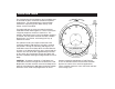
PRESS FEED TIMING The Reciprocating Linear Motion of the Feed Slide must be timed to the press crankshaft rotation for optimum performance. The Actuating Valve’s vertical motion controls the sequencing of the Stock Clamp, Feed Clamp, and the Feed Slide. To understand how the rotary crankshaft and linear Feed Slide motion work together in a Press Feed Cycle, it might be helpful to visualize a Clock Face.
AIR FEED SEQUENCE • • • • Actuating Valve up Feed Slide forward Stock Clamp open Feed Clamp closed AT TOP OF PRESS STROKE • • • • Actuating Valve down Stock Clamp closes Feed Clamp opens Feed Slide moves back AT BEGINNING OF NON-FEED STROKE • • • Feed Slide rests against Stop Screw Stock Clamp closed Feed Clamp open AT END OF NON-FEED STROKE • • • • Actuating Valve up Feed Clamp closes Stock Clamp opens Feed Slide moves forward AT BEGINNING OF FEED STROKE 7
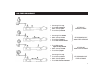
CONTROLLING THE FEED MECHANICAL ACTUATION Install a Support Bar with a Plunger on the upper Die Block of the Tool or on the Press Ram. The vertical Plunger should be threaded to allow vertical height adjustments. The Plunger should contact the center of the Feeder’s Actuating Valve Stem. After contact, and during the first 1/4" (6mm) of downward Valve Stem travel, nothing happens with the Feed Slide Control.
CONTROLLING THE FEED REMOTE PNEUMATIC ACTUATION By removing the Mechanical Actuating Valve Assembly, the timing control of the feed cycle can be changed by installing the optional Piston Operated Valve (POV). The Feed Cycle is then controlled by a cam operated 3-Way Spool Valve and a Linear Cam mounted on the Press Ram, or by a Rotary Cam mounted on the crankshaft.
CONTROLLING THE FEED REMOTE ELECTRIC ACTUATION To control the timing of the Feed Slide motion electrically, install the 3-Way Solenoid Valve on top of the P.O.V. and wire into a Limit Switch. Mounting a Linear Cam on the Press Ram Slide or installing a Rotary Cam on the crankshaft are two ways to electrically control the Feed Cycle. Many new presses today are equipped with electronic Programmable Controllers and/or electronic Rotary Limit Switches. Specify 24 VDC for Solenoid Valve.
CONTROLLING THE FEED REPEATER CONTROL SYSTEM The Air Feed can be multiple stroked for each cycle of the Press to obtain greater feed length increments than the Air Feed’s maximum feed stroke capacity. The Repeater Control has a digital counter and Key Lock Selector Control for “Feed Control Press” or “Press Control Feed”. Used with Remote Electric Actuation and 120 VAC, 50/60 Hz Power Supply. Transformers for other voltages are available.
MATERIAL ADJUSTMENT STEP 1. The strip material must be straight and parallel from the Rear Stock Guides through the Feed and into the Tool. STEP 3. Recommended vertical clearance between the Material and the two Clamps is .010" to .020" (.3mm to .5mm). Adjust by holding the Clamp Piston Stem with a Hex Key and turn the Hex Nut. STEP 2. Adjust the two Roller Stock Guides with enough lateral clearance for camber and variations in stock width.
SPEED CONTROL The Speed Adjustment Screw is located on the side opposite the air inlet. It provides material velocity control during the feeding direction of the Feed Slide. HOW TO SET 1. Cycle the Feed manually, turning the Speed Adjustment Screw clockwise until the Feed motion becomes erratic or incomplete. SAFE WORKING SPEEDS AT VARYING LENGTHS MODEL AX 2. Turn the Speed Adjustment Screw counter-clockwise until Feed Slide makes a complete forward motion. 3.
THREE PILOT RELEASE METHODS MECHANICAL PILOT RELEASE The Mechanical Spring-Loaded Pilot Release Clamp is installed in place of the standard Stock Clamp. Turn the Hex Nut to compress the Spring for the desired clamp and material pressure. Not available on LX. PNEUMATIC PILOT RELEASE The Pneumatic Pilot Release can be used for those applications that require more sensitive clamping pressure, or that the Clamp pad be completely free of the material.
FEEDING SHAPED MATERIAL By machining the grip side of the Clamps to the desired contour, any kind of material or preformed parts like electronic contacts, terminals, or wire, tubing, and channel can be easily handled. STANDARD CLAMPS PROTECTIVE COVERS P/A Industries strongly recommends our rugged, see-through Cover of Plexiglas or Expanded Metal for operator protection. Pre-drilled holes in the Feed Guide Rail accept the Slip-Fit Fasteners that secure the Cover over the top and sides of the Feed.
MODEL AX PARTS LIST ( ) Indicates quantity used if more than one Item 1 2 3 4 5 6 7 8 9 11 12 13 14 15 16 17 18 20 21 22 23 24 25 26 27 28 29 31 32 33 34 36 37 40 41 42 43 45 46 47 49 50 51 52 53 56 57 58 59 61 62 63 64 65 67 74 75 16 Description Valve Block O-Ring Ring Insert Valve Stem Valve Disc O-Ring Hex Nut Screw Gasket, Valve Block Cartridge Valve Valve Plug O-Ring O-Ring Screw Washer Collar, Spacer - Loctite #609 O-Ring Screw Stock Clamp Piston O-Ring Spring, Compression Pilot Release Clamp Spring
MODEL AX 17
MODELS CX, DX PARTS LIST ( ) Indicates quantity used if more than one Item 1 2 3 4 5 6 7 8 9 11 12 13 14 15 16 17 18 20 21 22 23 24 25 26 27 28 29 30 31 32 33 34 36 37 39 40 41 42 43 45 46 47 48 49 50 51 52 53 54 56 57 58 59 60 61 62 63 18 Description Valve Block O-Ring Ring Insert Valve Stem Valve Disc O-Ring Hex Nut Screw Gasket, Valve Block Cartridge Valve Valve Plug O-Ring O-Ring Screw Washer Piston Guide O-Ring Screw Stock Clamp Piston O-Ring Spring, Compression Pilot Release Clamp Spring Stud Spring
MODELS CX, DX REPAIR KITS Model CX – P/A No. 15926 Model DX – P/A No. 15927 Repair Kits include these Item Numbers: 2, 5, 6, 9, 11, 13, 14, 18, 22, 23, 28, 30, 31, 33, 34, 39, 41, 46, 47, 48, 49, 51, 57, 59, 61, 64, 70, 73, 87, 96, 98 REPAIR KIT includes a complete set of O-Rings, Cartridge Valve, Gaskets, Piston Seal, Guide Bushing, Springs, Valve Disc, and Exhaust Silencers.
MODELS FX, HX, LX PARTS LIST ( ) Indicates quantity used if more than one Item 1 2 3 4 5 6 7 8 9 11 12 13 14 15 16 17 18 20 21 22 23 24 25 26 27 28 29 30 31 32 33 34 36 37 39 40 41 42 43 44 45 46 47 48 49 50 51 52 53 54 56 57 58 59 60 61 62 20 Description Valve Block O-Ring Ring Insert Valve Stem Valve Disc O-Ring Hex Nut Screw Gasket, Valve Block Cartridge Valve Valve Plug O-Ring O-Ring Screw Washer Piston Guide O-Ring Screw Stock Clamp Piston O-Ring Spring, Compression Pilot Release Clamp Spring Stud Sp
MODELS FX, HX, LX REPAIR KITS Model FX – P/A No. 15928 Model HX – P/A No. 16751 Model LX – P/A No. 16935 Repair Kits include these Item Numbers: 2, 5, 6, 9, 11, 13, 14, 18, 22, 23, 28, 30, 31, 33, 34, 39, 41, 46, 47, 48, 49, 51, 57, 59, 61, 64, 70, 73, 87, 96, 98 REPAIR KIT includes a complete set of O-Rings, Cartridge Valve, Gaskets, Piston Seal, Guide Bushing, Springs, Valve Disc, and Exhaust Silencers.
FEED ACTUATION METHODS See pages 9 and 10 for schematics 92 92 PNEUMATIC SIGNAL ELECTRIC SIGNAL PNEUMATIC SIGNAL 91 REMOTE ACTUATION MECHANICAL ACTUATION MODEL AX 22 ELECTRIC SIGNAL 91 MECHANICAL ACTUATION REMOTE ACTUATION MODELS CX, DX, FX, HX, LX ACCESSORIES
PILOT RELEASE ACTUATION METHODS PNEUMATIC SIGNAL ELECTRIC SIGNAL 117 93 See page14 for schematics PNEUMATIC SIGNAL 93 ELECTRIC SIGNAL PNEUMATIC SIGNAL ELECTRIC SIGNAL 117 * ALREADY INSTALLED IN AIR FEED MECHANICAL PILOT RELEASE REMOTE PILOT RELEASE MODEL AX MECHANICAL PILOT RELEASE REMOTE PILOT RELEASE INTERNAL PILOT RELEASE MODELS CX, DX, FX, HX MODELS CX, DX, FX, HX, LX MODELS LX 23
TROUBLE SHOOTING CHART FEEDS SHORT Strip Moves Under Feed Clamp Strip Moves Under Stock Clamp ✔ ✔ ✔ ✔ ✔ ✔ ✔ ✔ FEEDS LONG AND SHORT FEEDS LONG Feed Slide Not Making Full Stroke Feed Slide Moves Before Feed Clamp Closes Strip Moves Under Feed Clamp Strip Moves Under Stock Clamp FEED SLIDE Moves To Stock Stop Buckles Screw AIR LEAKAGE Exhaust Port No Valve Main Motion Block Body Air Tubes SET-UP & OPERATION Air Pressure or Volume Too Low Feed Mounted Loose or Misaligned Obstruction within Die:
WARRANTY We warrant our new parts against defects under normal use and service for a period of 2 years after date of shipment. Our obligation under this warranty is limited to replacing or repairing (at our option) the defective part without charge, F.O.B. our plant in Bloomfield, Connecticut. The defective part must be forwarded to our plant, freight-prepaid, for our inspection prior to replacement or repair.
® P/A INDUSTRIES INC. P / A Te c h n o l o g y Pa r k 522 Cottage Grove Road Bloomfield, CT 06002 USA Toll Free: 1-800-243-8306 Worldwide: 1-860-243-8306 Fax: 1-860-242-4870 E-Mail: sales@pa.com Webpage: http.//www.pa.