
Owner manual

Form 1145 Mini Installation Form and Operation Manual 02/02/2006
20
6. PNEUMATIC PILOT RELEASE
During operations such as forming or using pilots, the purpose of the Pneumatic Pilot Release is to release the strip
from being held by the feeder rolls. This allows the material to be adjusted slightly any time during the press cycle.
The pneumatic release mechanism is mounted centrally on the top of the feeder using (4) M8 screws and washers in
slotted holes. The slots are to allow proper alignment and adjustment with the release arm and roller.
Open the rolls allowing clearance between the upper roll and the material approximately 0.010”/0.25 mm.
(Use a shim on top of the material, if needed.)
Position the Pilot Release mechanism so that with the cylinder piston fully extended against the roller.
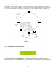
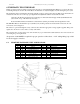
The SRF Pilot Release mechanism is pre-assembled, only needing outside air and electrical connections. For air
connections, refer to Figure 6.
The release is operated through the 3-way solenoid valve when the appropriate voltage signal is applied. This power
signal can come from a source such as a rotary cam switch.
The solenoid valve, located on the side of the feeder body, is provided with a cable attached to the solenoid valve for
connecting the power signal leads.
Air pressure of 80-100 PSI is required for proper operation of the release. A 1/4” tubing fitting is provided
for the air supply connection.
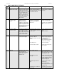
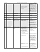
6.1 PILOT RELEASE PARTS LIST AND DIAGRAM
Item Q-ty Description Item Q-ty Description
01 01 Bracket 12 01 Straight fitting
02 01 Silencer 13 01 Elbow fitting
05 02 Screw, M6x20 14 01 Elbow fitting
06 01 ScrewM8x25, flat head 15 01 Pneumatic cylinder
07 02 Flat washer, M6 16 01 Straight fitting
08 01 Hex nut, M8 17 04 Tubing
09 04 Screw, M8x25 18 03 Screw, M3x20
10 01 3 way valve, 24VDC 19 01 Silencer
11 01 Valve solenoid cable