Form 1145 Mini Installation Form and Operation Manual 1 02/02/2006
Form 1145 Mini Installation Form and Operation Manual 02/02/2006 RECEIVING INSPECTION Before removing unit from its packaging, check for visual damage, especially if crate, skid, or carton has been damaged in transit. Any damage caused by shipping should be immediately reported to the carrier. If unit appears in satisfactory condition, remove all packing and wipe rust preventive from rollers with mild solvent. TABLE OF CONTENTS DESCRIPTION PAGE RECEIVING INSPECTION.....................................
Form 1145 Mini Installation Form and Operation Manual 02/02/2006 1. INTRODUCTION The P/A Industries Mini Servo Roll Feed is a state of the art AC Servo feed, which eases operator adjustments to feed pitch, speed, and acceleration. These operator adjustments are entered into the control memory by keypad input. With the use of a positional limit switch, the press signals the feeder when to begin moving the strip.
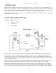
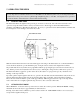
Form 1145 Mini Installation Form and Operation Manual 02/02/2006 end result is an accurately positioned strip exactly 5.566 inches from its starting point. This entire process happens in milliseconds. 3.INSTALLING YOUR “MINI” SERVO FEED 3.1 MECHANICAL INSTALLATION The Mini Servo Roll Feed is supplied with an adjustable mounting bracket. The feed should be securely mounted to the press frame. (A transition bracket is sometimes required in certain applications.
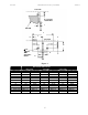
Form 1145 Mini Installation Form and Operation Manual 02/02/2006 PASS LINE DF K - PASS LINE ADJUSTMENT J BOLSTER C A B F PASS LINE H ∅0.551’’ (∅14MM) THRU MOUNTING HOLES E G D Figure 2 DIMENSION A B C D E F G H J K - PASS LINE ADJUSTMENT MOUNTING DIMENSIONS SRF-105M SRF220M SRF-320M INCHES MILLIMETERS INCHES MILLIMETERS INCHES MILLIMETERS 4.63 117.50 6.89 175.00 8.86 225.00 1.77 45.00 1.77 45.00 1.77 45.00 9.25 235.00 13.78 350.00 17.72 450.00 1.97 50.00 3.94 100.00 3.94 100.00 3.94 100.00 7.
Form 1145 Mini Installation Form and Operation Manual 02/02/2006 4. PROGRAMMING THE “MINI” IMPORTANT! Before turning the system on for the first time, verify that the main input voltage is correct (115 VAC single phase) and inspect all connections for tightness, shorts, etc. Plug the 115 VAC plug into a clean 10 Amp supply (15 Amp for SRF-320 model. Press the amber ‘POWER ON’ push button. The button will illuminate and the data input display will be visible.
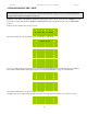
Form 1145 Mini Installation Form and Operation Manual Getting Speed Getting Accel 02/02/2006 At this point a servo feed ready for normal operation. Units of measure are displayed in inches or meters/millimeters, depending on the value of the scale parameter. Standard Scale values are: 4106.7 counts/inch and 161.7 counts/mm. 1 Length:2.54 in 2 Speed:100 in/s 3 Accel:400 in/s^2 Enter choice: 1 Length:25.4 2 Speed:2.
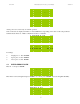
Form 1145 Mini Installation Form and Operation Manual LengTh:3.00 New Length: in PresS ENTER to exit To exit, press ‘ENTER’ (leave the Length field blank). 1 Length:3.00 in 2 Speed:100.00 in/s 3 Accel:400.0 in/s^2 Enter choice: The maximum feed Length that may be entered is 999999 inch or mm. 4.2 ENTER FEED SPEED Enter in ‘2’ and press ‘ENTER’ 1 Length:3.00 in 2 Speed:100.00 in/s 3 Accel:400.
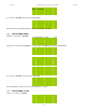
Form 1145 Mini Installation Form and Operation Manual Accel:400.0 New Accel: 02/02/2006 in/s^2 Press ENTER to exit Enter in the new Accel and press ‘ENTER’ or to cancel, press ‘ENTER’ (leave the Accel field blank). Accel:400.0 New Accel:600 Press ENTER to exit Accel:600.0 New Accel: in/s^2 Press ENTER to exit To exit, press ‘ENTER’ (leave the Accel field blank). 1 Length:3.00 in 2 Speed:120.00 in/s 3 Accel:600.
Form 1145 Mini Installation Form and Operation Manual 02/02/2006 5. OPERATING THE FEED NOTE: It is very important to remember that the motor on The Mini Servo Roll Feed System is only for feeding material. It is not intended to be the power source for a pull-through straightening device, or the like. An adequate free loop must be provided at all times. This will assure consistent and accurate feeding. 5.1 LOADING THE FEED The material should be brought from the powered pay off device to the feeder.
Form 1145 Mini Installation Form and Operation Manual 02/02/2006 NOTES ABOUT "POSSIBLE PROBLEM TOOLING" • A tight die, one that is not square, or has other tooling problems, will cause significant difficulty and downtime. Accuracy in feeding is directly related to how easily the feeder can position the strip in the die. Binding, bad part ejection, or sticking parts may cause the material to “jam” in the die.
Form 1145 5.3 Mini Installation Form and Operation Manual 02/02/2006 FEED INDEX SIGNAL The Mini Servo Roll Feed requires one signal to control the feed indexing. This signal initiates the start of feeding, and is usually set to occur as soon as the die is open. The duration of the feed signal should be at least 30 milliseconds (ms). The feed signal should be ‘OFF’ at the top of the press stroke to prevent double feed indexes. (See Figure 5.
Form 1145 5.5 Mini Installation Form and Operation Manual 02/02/2006 SERVO DRIVE FAULT TABLE Fault Fault Name Number Non-Volatile Memory 1 Endurance Exceeded 2 Position Change Exceeds Position Rollover Fault Description Range of motion and number This is an unrecoverable fault, of home position definitions the drive must be sent back to during the product life exceeds the factory the maximum allowed.
Form 1145 Mini Installation Form and Operation Manual 02/02/2006 the continuous power rating. Increase Motion Time or allow dwell periods. Reduce acceleration rates. Ultra3000 has a bad IPM output, short circuit, or overcurrent, Remove all power and motor connections, and then check continuity from the DC bus to U, V, and W outputs. If continuity exists, check for conductive materials between terminals. Replace the Ultra3000 drive.
Form 1145 Mini Installation Form and Operation Manual 02/02/2006 by hand. If difficult to turn by hand, the motor needs to be repaired or replaced. 11 Illegal Hall State ON indicates there is a problem with the motor's Hall Effect sensors. Incorrect phasing Check the Hall phasing. Bad connections Verify the Hall wiring. Verify power supply to encoder. 12 Home Search Failed ON indicates that the home Home sensor or marker is position was not found. outside the overtravel limit.
Form 1145 Mini Installation Form and Operation Manual Bad encoder 21 Auxiliary Encoder State ON indicates the auxiliary encoder encountered an illegal transition. 02/02/2006 Replace motor/encoder. Auxiliary encoder encountered Use shielded cables with an illegal transition twisted pair wires. Route the encoder cable away from potential noise sources. Bad encoder - replace encoder. Check the ground connections. Setup time violation for Step/Direction or CW/CCW input.
Form 1145 29 Excessive Output Frequency Mini Installation Form and Operation Manual ON indicates the motor encoder output frequency exceeds the maximum value. Encoder output frequency exceeds the maximum value. 02/02/2006 Increase the encoder output maximum frequency parameter. Decrease the encoder interpolation parameter. Note: This fault can only be generated when the encoder output is synthesized by the Ultra3000.
Form 1145 35 36 Soft-Starting Fault Power Module Overtemperature Mini Installation Form and Operation Manual ON indicates a soft fault at startup. ON indicates an overtemperature condition in the power module. 02/02/2006 Internal malfunction Disconnect motor power cable from drive and enable drive with current limit set to 0. If fault remains, call your A-B representative. If fault clears, a wiring error or an error internal to the motor exists.
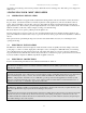
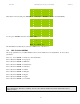
Form 1145 5.6 Mini Installation Form and Operation Manual 02/02/2006 SPEED PERFORMANCE GRAPH The speed performance graph shown below is to be used as a guide only. Actual feeder/press speeds may vary depending on factors such as material thickness, width, rigidity, surface finish, and free loop. Strokes Per Minute 700 600 Feed Angle (degrees): 500 270 180 90 400 300 200 100 0 0 1 2 4 6 8 10 14 18 22 Feed Length, Inches Figure 6.
Form 1145 Mini Installation Form and Operation Manual 02/02/2006 6. PNEUMATIC PILOT RELEASE During operations such as forming or using pilots, the purpose of the Pneumatic Pilot Release is to release the strip from being held by the feeder rolls. This allows the material to be adjusted slightly any time during the press cycle. The pneumatic release mechanism is mounted centrally on the top of the feeder using (4) M8 screws and washers in slotted holes.
Form 1145 Mini Installation Form and Operation Manual 02/02/2006 7. MAINTENANCE The Mini Servo Roll Feed needs very little maintenance to keep the system operating at its optimum performance. • This precision equipment must be kept as clean as possible. This is especially important if large amounts of air suspended oil mists in combination with “dirty metals” are used. The resulting abrasive dust can attach itself to the feed rolls and other surfaces, leading to premature wear on many parts.
Form 1145 Mini Installation Form and Operation Manual 02/02/2006 List of parts that are different between 105M through 320M models Item 05 15 19 20 24 25 31 32 33 38 40 41 42 44 50 Q-ty 01 01 01 01 01 02 01 01 01 01 01 01 01 01 01 105M Part # R-SRF-105M-05 R-SRF-105M-15 R-SRF-105M-19 R-SRF-105M-20 R-SRF-105M-24 R-SRF-105M-25 R-SRF-105M-31 R-SRF-105M-32 R-SRF-105M-33 R-SRF-105M-38 R-SRF-105M-40 R-SRF-105M-41 R-SRF-105M-42 R-SRF-105M-44 R-SRF-105M-50 220M Part # R-SRF-220M-05 R-SRF-220M-15 R-SRF-220M-19
Form 1145 Mini Installation Form and Operation Manual 02/02/2006 WARNING This equipment offers various means of operating or controlling machines. The operator must not be in or near the point-ofoperation of the machine, or the operating parts of any equipment installed on the machine, or bodily injury could result. The EMPLOYER must post adequate warning signs onto the machine with proper warnings for his machine and the specific application to which the machine and equipment are being applied.