ULTRA MAGNUM SERVO ROLL FEED 2 /14/2003 TABLE OF CONTENTS DESCRIPTION PAGE 1 INSTALLATION ......................................................................................................................................................3 1.1 MECHANICAL INSTALLATION ...................................................................................................................3 1.2 ELECTRICAL INSTALLATION ...............................................................................................
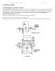
ULTRA MAGNUM SERVO ROLL FEED 2 /14/2003 1 INSTALLATION 1.1 MECHANICAL INSTALLATION The Ultra Magnum Servo Roll Feed is supplied with an adjustable mounting bracket. The feed should be securely mounted to the press frame. (A transition bracket is sometimes required in certain applications.) The feed should be centered, square, and perpendicular to the pass line of the press. It should be mounted at a height that will accommodate the appropriate die sets. The feed has a pass line height adjustment of ±2.
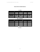
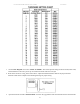
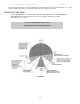
ULTRA MAGNUM SERVO ROLL FEED 2 /14/2003 MOUNTING DEMENSIONS INCHES B 24.4 30.5 36.4 44.5 48.4 60.2 MODEL SRF-M12 SRF-M18 SRF-M24 SRF-M32 SRF-M36 SRF-M48 A 12.2 15.3 18.2 22.3 24.2 30.1 MODEL SRF-M12 SRF-M18 SRF-M24 SRF-M32 SRF-M36 SRF-M48 MILLIMETERS A B 310 620 387 775 462 925 565 1130 615 1230 765 1529 FIGURE 2 4 C 26.4 32.5 38.4 46.5 50.4 62.2 D 18.4 24.4 30.4 38.3 42.4 54.
ULTRA MAGNUM SERVO ROLL FEED 2 /14/2003 1.2 ELECTRICAL INSTALLATION The Ultra Magnum Servo Roll Feed has been designed to make electrical connections quickly and easily. All that is required is a "clean" 220 VAC single-phase 20-ampere source that must be connected to the main disconnect switch. It is recommended that #12 MTW (Machine Tool Wire) be used for the primary power supply input. The inputs and outputs to your press control (i.e.
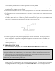
ULTRA MAGNUM SERVO ROLL FEED 2 /14/2003 1.3 PLS ENCODER INSTALLATION (OPTIONAL) The PLS encoder must be mounted on the press so its shaft is coupled or belted to the crankshaft with one to one (1:1) ratio. It is strongly recommended to use plastic or aluminum sprockets on the encoder shaft. When all required electrical connections are made, power up the feed control and bring up the Status screen: Tool#1 Pos:182 Manual Mode 30 / Cont.
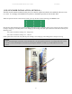
ULTRA MAGNUM SERVO ROLL FEED 2 /14/2003 1.4 STRIP ENCODER INSTALLATION (OPTIONAL) The Strip Encoder comes pre-installed on the feed body and all it needs is proper electrical connections and air pressure of 80-100 PSI to the pressure regulator mounted on the front side of Strip Encoder Assembly. 1.5 LOADING THE FEED FIGURE 3 Prior to this step, the electrical control must be powered up and all needed parameters are loaded. (Refer to the Ultra Magnum Servo Feed Operating Manual.
ULTRA MAGNUM SERVO ROLL FEED 2 /14/2003 1. `Put the Ultra Magnum control into “MANUAL MODE”. Record the present settings of the Feed Cam, Reset Cam, and Pilot Release Cam into a job set-up record sheet for future reference to the job. 2. Refer to the Thickness Setting Chart shown above. Adjust the material thickness dial for the proper material thickness. Refer to the example in the following drawing for proper setting. 3. Open the feed rolls with the “OPEN/CLOSE” switch on the jog pendant.
ULTRA MAGNUM SERVO ROLL FEED 2 /14/2003 4. Adjust the roll clamping pressure via the pressure regulator located on the material inlet side of the feed in the top cover. Adjust the pressure until the liquid filled gage reads approximately 40 PSI. 5. Using the Jog Forward button on the jog pendant, advance the material up to the entrance of the die (far enough where the punches would not pierce the material). 6. Check the vertical alignment of the strip.
ULTRA MAGNUM SERVO ROLL FEED 2 /14/2003 press through another stroke, verifying that things are happening at the correct time (Roll Release, etc.). If the system is operating properly, you can make a few more “hits”, checking your parts. 1.6 RUNNING THE FEED Put the Ultra Magnum into “Auto” mode and press the Cycle Start button. The Ultra Magnum Servo Roll Feed will now follow the press until it is stopped by the Operator, counter, emergency stop, or feed error.
ULTRA MAGNUM SERVO ROLL FEED 2 /14/2003 NOTES ABOUT ‘POSSIBLE PROBLEM TOOLING’: * o A tight die, one that is not square, or has other tooling problems, will cause significant difficulty and downtime. Accuracy in feeding is directly related to how easily the feeder can position the strip in the die. Binding, bad part ejection, or sticking parts may cause the material to "jam" in the die. o The Ultra Magnum Servo Roll Feed will "try" to overcome the "jam-up" by applying more power to the rolls.
ULTRA MAGNUM SERVO ROLL FEED 2 /14/2003 3 MAINTENANCE The Ultra Magnum Servo Roll Feed needs very little maintenance to keep the system operating at its optimum performance. o This precision equipment must be kept as clean as possible. This is especially important if large amounts of air suspended oil mists in combination with “dirty metals” are used. The resulting abrasive dust can attach itself to the feed rolls and other surfaces, leading to premature wear on many parts.
ULTRA MAGNUM SERVO ROLL FEED 2 /14/2003 4 ROLL FEED PARTS LIST MECHANICAL PARTS LIST AND DIAGRAM ITEM 1. 2. 3. 4. 5. 6. 7. 8. 9. 10. 11. 12. 13. 14. 15. 16. 17. 18. 19. 20. 21. 22. 23. 24. 25. 26. 27. 28. 29. 30. 31. 32. PART NO.
ULTRA MAGNUM SERVO ROLL FEED ITEM 33 34 35 36 37 38 39 40 41 42 43 44 45 46 48 49 50 51 53 54 56 57 58 59 60 61 62 63 64 65 66 PART NO.
ULTRA MAGNUM SERVO ROLL FEED 2 /14/2003 15
ULTRA MAGNUM SERVO ROLL FEED 2 /14/2003 16
ULTRA MAGNUM SERVO ROLL FEED ITEM 1 2 3 4 5 6 7 PART NO. 12039-80 12039-81 12022-95 12022-99 12024-17 12019-15 16286-05 2 /14/2003 QTY 1 1 1 1 1 1 1 17 DESCRIPTION VALVE, SOLENOID-AIR SUBASE, VALVE MOUNTING VALVE, PRESSURE REG. BRACKET, REG. MOUNTING SILENCER, AIR GAGE, PRESSURE-BAR. SUPPRESSOR, SOL.
ULTRA MAGNUM SERVO ROLL FEED 2 /14/2003 3 2 1 ITEM PART NO.
ULTRA MAGNUM SERVO ROLL FEED 2 /14/2003 5 CASCADE WITHOUT ENCODER PARTS LIST & DIAGRAM ITEM 1 2 3 4 5 6 7 8 9 10 11 12 13 14 21 PART NO.
ULTRA MAGNUM SERVO ROLL FEED 2 /14/2003 20
ULTRA MAGNUM SERVO ROLL FEED 2 /14/2003 6 CASCADE WITH ENCODER PARTS LIST & DIAGRAM ITEM 1 2 3 4 5 6 7 8 9 10 11 12 13 14 15 16 17 18 21 22 PART NO.
ULTRA MAGNUM SERVO ROLL FEED 2 /14/2003 22
ULTRA MAGNUM SERVO ROLL FEED 2 /14/2003 7 OPTIONAL STRIP ENCODER PARTS LIST & DIAGRAM ITEM PART NO.
ULTRA MAGNUM SERVO ROLL FEED 2 /14/2003 24
WARNING This equipment offers various means of operating or controlling machines. The operator must not be in or near the point-ofoperation of the machine, or the operating parts of any equipment installed on the machine, or bodily injury could result. The EMPLOYER must post adequate warning signs onto the machine with proper warnings for his machine and the specific application to which the machine and equipment are being applied. Occupational Safety and Health Act (OSHA) Sections 1910.211, 1910.