
Installation and Operating Instructions Owner's manual
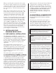
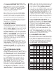
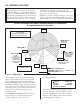

3.4 MAGNUM MOUNTING HOLES
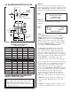
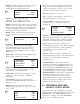
STEP #1:
Turn on the main power disconnect switch. This
applies power to the control power supply. Press the
amber ‘
POWER ON’ push-button. The button will
illuminate and the data input display will be visible:
☞
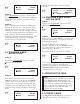
STEP #2:
Press any key on the terminal, the display
will show:
☞
STEP #3:
The ‘POWER ON’ push-button has a ‘FAULT
RESET
’ function built into the button. Press the
‘
POWER ON’ button to clear the ‘ENCODER
FAULT
’ message at the bottom line of the display.
The feed may now be jogged forward by pressing
the ‘
JOG FORWARD’ button, or jogged in reverse
by pressing the ‘
JOG REVERSE’ button.
The Magnum Servo Roll Feed has six viewable
screens. Only the first operator screen (shown
above) will be operator editable/programmable.
This screen displays the length, count, and speed
parameters. These parameters may only be changed
while the program is stopped (indicated by lack of
‘
CYCLE START’ or set up light). The other
viewable screens are shown on the following page.
These five other screens will be viewable at all times,
but are “locked” out of programming via run/prog
switch located on the electrical panel inside the
electrical enclosure. The factory set parameter
values for the Magnum Servo Roll Feed are printed
on the operator panel below the operator terminal.
These parameters are set from the factory for
average feeding applications and they seldom
require any changes. The five screens and a brief
explanation of the parameters are described below:
• LENGTH: Distance in inches (or millimeters) of
the feed length. Maximum value of 999.750
inches.
• COUNT: The number of pieces required to run
in the batch. Maximum value of 999,999 pieces.
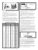
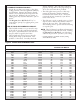
MODEL A B C D
SRF-M12 310 620 670 467
SRF-M18 387 775 825 619
SRF-M24 462 925 975 772
SRF-M32 565 1130 1181 972
SRF-M36 615 1230 1280 1076
SRF-M48 765 1529 1580 1377
4
P/A INDUSTRIES
SERVO ROLL FEED
VERSION 1.00
HIT KEY TO CONT__
LENGTH 00008.000
COUNT 100000
SPEED 0060/SEC
ENCODER FAULT
C
D
4.3” (109mm)
3.1” (80mm)
5.9”
(150mm)
B
A
DRAWING 17573-02
PASS LINE
HEIGHT
ADJUSTMENT
±
2.0”
ø0.67” (ø17mm)
(4) MOUNTING
HOLES
PASS LINE
MILLIMETERS
MODEL A B C D
SRF-M12 12.2 24.4 26.4 18.4
SRF-M18 15.3 30.5 32.5 24.4
SRF-M24 18.2 36.4 38.4 30.4
SRF-M32 22.3 44.5 46.5 38.3
SRF-M36 24.2 48.4 50.4 42.4
SRF-M48 30.1 60.2 62.2 54.2
INCHES
MAGNUM MOUNTING HOLES
for drawing 17573-02
Figure 2.
4. PROGRAMMING THE MAGNUM
SERVO FEED SYSTEM
IMPORTANT !
Before turning the system on for the first time,
verify that the main input voltage is correct
(220vac single phase) and inspect all connections
for tightness, shorts, etc.