® Installation and Operating Instructions MAGNUM SERVO FEED MODELS SRF-M12 / 18 / 24 / 32 / 36 / 48 P/A INDUSTRIES INC. 522 Cottage Grove Road • Bloomfield, Connecticut 06002-3191 U.S.A. Toll Free 1-800-243-8306 • Worldwide 1-860-243-8306 • Fax 1-860-242-4870 Website http://www.pa.com • E-Mail service@pa.
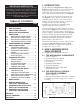
RECEIVING INSPECTION 1. INTRODUCTION TABLE OF CONTENTS A high strength cast iron frame forms the core of the Magnum. Large diameter textured feed rolls with driven upper and lower rolls assure positive feeding of the strip without slipping. A precision worm-gear reducer provides the torque multiplication necessary for optimum pulling capacity required on heavier material.
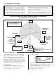
Quick connectors. The electrical Control Enclosure is supplied with a stand/support which may be placed in any convenient location. The enclosure may also be mounted in any fixed location as long as cabling is adequate to reach the feeder. It is not recommended that the Electrical Enclosure be mounted directly to the press. The vibrations caused by the press may result in damage to the control system.
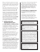
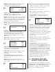
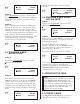
3.4 MAGNUM MOUNTING HOLES STEP #1: Turn on the main power disconnect switch. This applies power to the control power supply. Press the amber ‘POWER ON’ push-button. The button will illuminate and the data input display will be visible: PASS LINE HEIGHT ADJUSTMENT ± 2.0” ☞ 4.3” (109mm) DRAWING 17573-02 P/A INDUSTRIES SERVO ROLL FEED VERSION 1.00 HIT KEY TO CONT__ STEP #2: D Press any key on the terminal, the display will show: ☞ PASS LINE 5.9” (150mm) LENGTH 00008.
• SPEED: The maximum velocity of the material • KP: Proportional gain parameter for the motion in inches/second (or millimeter/second). Maximum value of 60 inches/second. ☞ ACCEL DWELL DBNC control. It controls the transitions between the starting and stopping of the rolls. A lower value provides a smoother (slower) transition. 000402/SEC^2 00.00 1 X 3.75MS • KD: This parameter is not used. • KFF: Velocity feed forward gain. This is used to reduce following error of the system.
☞ LENGTH COUNT SPEED After the first Index/Part is made, the display will show: 00008.000 100000 0060/SEC ☞ STEP #1: LENGTH 00001.253 COUNT 001000 SPEED 0060/SEC 000001 / 001000 The ‘UNDERLINE’ type cursor is located under the length display whenever this screen is called up. This indicates that this entry is capable of being modified. 4.3 PROGRAM A NEW SPEED FOR THE FEED STEP #2: Position the ‘UNDERLINE’ type cursor under SPEED with the ◗ key. STEP#1: Enter a new feed length; for instance...1.
MODE’. The mode is selected through an input to the choose between ‘PRESS-BEFORE-FEED’ (PBF) and ‘FEED-BEFORE-PRESS’ (FBP) operating mode. feed controller. The press single stroke/continuous mode switch should be interfaced to this input for proper operation. During ‘SINGLE STROKE’ mode operation, the ‘PERMIT PRESS’ output relay is activated upon the completion of each feed index. The ‘PERMIT PRESS OUTPUT RELAY’ remains active until the continue cam signal turns on.
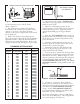
MATERIAL THICKNESS ADJUSTMENT HANDLE/WHEEL 00340 This reading = 3.40 mm (.134”) thickness PASS LINE ADJUST 3. Open the feed rolls with the ‘OPEN/CLOSE’ rolls switch on the jog pendant. Insert the material and close the feed rolls. 4. Adjust the roll clamping pressure via the pressure regulator located on the material inlet side of the feed in the top cover. Adjust the pressure until the liquid filled gage reads approximately 40 psi. 5.
5.5 RUNNING THE FEED NOTE ABOUT CAMS: The Feed Advance Cam (open tool): The feed system uses this press cam for timing the feeder to the press crankshaft. Although no shafting or belts actually connect the press to the feeder, the feed must be “told” when it is safe to move the strip and when the feed move must be completed. • This “connection” is an electrical one, and not a mechanical one. This gives the operator/set-up personnel total flexibility in deciding when the feed progression should take place.
NOTES ABOUT "POSSIBLE PROBLEM TOOLING":* • A tight die, one that is not square, or has other did not "misfeed". The rolls were positioned properly, the strip did not keep up, causing the die to close and a miss-hit is produced. • The feed applies more power to a thin strip, causing the material to buckle somewhere between the feed and the die set. The feeder positioned the strip accurately, it just did not occur in the die set.
6. TROUBLESHOOTING GUIDE The chart that follows contains the most frequently encountered issues. SYMPTOM CAUSE or REMEDY No power indication when ‘POWER ON’ button is pressed • Check main power supply for proper voltage. No display on power up • Check cabling connection between display and servo drive. • Check 5 Volt logic supply LED on motion control card on right side of Servo Drive/Amplifier under orange connectors. • Check fuses in drive under right side cover.
Some errors encountered with the Magnum Servo Roll Feed may be diagnosed by the motion controller. These errors are typically displayed on the bottom line of the Operator Terminal Display. These errors are related to improper motion of the servomotor. These errors are listed below. These errors may be reset by either pushing ‘POWER ON’, which has a reset function, or by power-down and power-up. 6.
6.2 DDM DRIVE ERROR MESSAGES 6.4 POWER-UP ERROR CODES If there is a fault, the drive provides specific error messages. Faults are detected by the drive in two ways: power-up hardware and run-time faults. A power-up fault usually requires servicing of the hardware. A run-time fault can be cleared by resetting the drive. The Status display on the front of the servo drive module indicates faults by flashing the letter ‘E’, followed by additional digits to indicate the error.
• The main drive belt should be checked periodically for tightness. It can be adjusted by loosening the two fasteners on the motor adjuster plate, applying downward pressure on the motor adapter plate, and retightening. ERRATIC MOTOR BEHAVIOR WILL BE EXPERIENCED IF THE DRIVE BELT IS LOOSE! • The Feeder’s electrical enclosure door is sealed to prevent oil and contaminants from entering inside. However, small gaps can be found around some sealing surfaces and faceplates.
MAGNUM MECHANICAL PARTS DIAGRAM 76 E See Sheet 4 100 PSI Pre-Plumbed by P/A Note: Pre-set at Factory. Do not adjust. Note: Use a good grade of hydraulic oil like Shell Tellus 32.
TOP COVER VIEW AT A–A TOP COVER NOT SHOWN VIEW AT C–C SHEET 2 OF 4 SHEET 3 OF 4 VIEW AT B–B VIEW AT D–D VIEW AT F–F UPPER ROLL CROSS SECTION VIEW AT G–G ROTATED 90° DEGREES WITH PIVOT MOUNTING ROTATED 90° DEGREES SHEET 4 OF 4 VIEW AT E–E ROTATED 90° DEGREES 16
9. CASCADE WITHOUT ENCODER PARTS LIST & DIAGRAM ITEM 1 2 3 4 5 6 PART NO. QTY D17443 B17444-XX B16548-XX A17093 A17091-XX C16542-XX 2 1 3 2 2 4 DESCRIPTION ITEM BRACKET, CASCADE SIDE ROD, AXLE-UPPER ROLL ROD, AXLE-LOWER ROLLS CLAMP, GUIDE BAR GUIDE BAR, EDGE ROLLERS ROLLER, CONVEYOR PART NO. QTY DESCRIPTION 7 A17445-XX 4 COVER, ROLLER 8 P12416-27 2 HANDLE, 12mm TAP 9 M16522-2 2 ASSEMBLY, EDGE GUIDE ROLL 21 16735-02 2 HANDLE, WIDTH GUIDE ADJUST.
10. CASCADE WITH ENCODER PARTS LIST AND DIAGRAM ITEM PART NO. QTY 1 2 3 4 5 6 7 8 9 10 11 12 D17443 B17444-XX A16548-XX A17093 A17091-XX C16542-XX A17445-XX M16522-02 P12416-27 SUPPLIES SUPPLIES SUPPLIES 2 1 3 2 2 4 4 2 2 14 14 2 13 SUPPLIES 6 DESCRIPTION ITEM BRACKET, CASCADE SIDE ROD, AXLE-UPPER ROLL ROD, AXLE-LOWER ROLLS CLAMP, GUIDE BAR GUIDE BAR, EDGE ROLLERS ROLLER, CONVEYOR COVER, ROLLER ASSEMBLY, EDGE GUIDE ROLL HANDLE, 12mm TAP WASHER, 1/2” ID x 1.06 OD x .09 THK. NUT, M12 X 1.
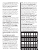
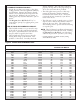
Installation & Operating Manual Programmable Limit Switch Job Set-Up Cam Function (Name) and Number “ON” Angle “OFF” Angle #1 Feed Advance 235° 90° #2 Continue Cam 180° 200° #3 Pilot Release 150° 180° #4 #5 #6 #7 #8 Typical Die Set-Up Chart Thickness Setting Chart Die No. __________ Mfg. Std. Gage No. Part No. _________ ______ No.
WARNING Of vital importance to any successful program is the proper selection of guards and devices. However, there is no safety device that will bring "automatic" safety to your operation. This equipment offers various means of operating or controlling machines. The operator must not be in or near the point-of-operation of the machine, or the operating parts of any equipment installed on the machine, or bodily injury could result.