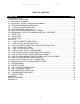
5/23/2003 ULTRA MAGNUM SERVO ROLL FEED TABLE OF CONTENTS DESCRIPTION PAGE 1 INTRODUCTION...................................................................................................................................... 3 2 THEORY OF OPERATION .................................................................................................................... 3 2.1 MECHANICAL ASSEMBLY ................................................................................................................... 3 2.
5/23/2003 ULTRA MAGNUM SERVO ROLL FEED RECEIVING INSPECTION BEFORE REMOVING UNIT FROM ITS PACKAGING, CHECK FOR VISUAL DAMAGE, ESPECIALLY IF CRATE, SKID, OR CARTON HAS BEEN DAMAGED IN TRANSIT. ANY DAMAGE CAUSED IN SHIPMENT SHOULD BE IMMEDIATELY REPORTED TO THE CARRIER. IF UNIT APPEARS IN SATISFACTORY CONDITION, REMOVE ALL PACKING AND WIPE RUST PREVENTIVE FROM ROLLERS WITH MILD SOLVENT.
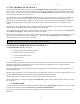
5/23/2003 ULTRA MAGNUM SERVO ROLL FEED ALL ULTRA MAGNUM SERVO ROLL FEED CONTROLS ARE CONVENIENTLY LOCATED ON THE FRONT SIDE OF THE ELECTRICAL ENCLOSURE CONTROL/DEVICE DESCRIPTION Power On/Reset button Turns controller on, resets the servo drive. In Position indicator light, white Turns on when move is complete and motor is holding position. Cycle Start illuminated button, green Turns controller into “Auto” mode from “Manual” mode, starts cycling.
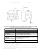
/23/2003 ULTRA MAGNUM SERVO ROLL FEED Each revolution of the servomotor produces 8000 encoder pulses. Every 25 revolutions of the servo motor shaft produce 1 revolution of the feed rollers. The circumference of the lower roll is approximately 14.781 inches. When a new feed pitch is entered into the system, the built in computer calculates the correct number of electronic “pulses” it must receive from the motor mounted encoder in order to rotate the feed rolls the correct distance.
5/23/2003 ULTRA MAGNUM SERVO ROLL FEED 2.5 PLS OPERATION (OPTIONAL) The PLS, Programmable Limit Switch consists of an intelligent encoder and the cable that connects the encoder to the servo drive. The encoder is mounted on the press and its shaft is coupled or belted to the crankshaft with a one to one (1:1) ratio. On every power-up, the encoder turns into the intelligent mode (for approximately 10 msec) to read its actual position and store it in the servo drive.
5/23/2003 ULTRA MAGNUM SERVO ROLL FEED 2. CHECK MODE In this mode the full control of the material motion (Acceleration, Deceleration, Speed and positioning) is done through the motor mounted encoder. When a move is complete, the Strip Encoder positioning control checks if the material is within the Length Check tolerance, if it is not, "Position Error" is displayed, and Auto mode is turned off.
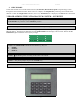
5/23/2003 ULTRA MAGNUM SERVO ROLL FEED 3.1 “OPER” KEY “OPER” key controls appearance of two screens: STATUS screen and OPERATOR screen. STATUS screen shows: Tool#1 Pos:182 Manual Mode 30 / Cont.Run Press a Mode Key • Active tool number. In case there is no active tool “No Tool!” message is displayed instead • Current press position in degrees.
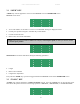
5/23/2003 ULTRA MAGNUM SERVO ROLL FEED Position the pointer on desired line, using “↑” and “↓” keys , and press the “ENTER” key. Enter in the tool number or select it from the tool list using “↑” and “↓” keys and press the “ENTER” key again. Edit Tool#1 Arrow keys to scroll Press TOOLS to exit Activate Tool#1 Arrow keys to scroll Press TOOLS to exit Create Tool# Press TOOLS to exit NOTE: Tool number can contain up to seven digits.
5/23/2003 ULTRA MAGNUM SERVO ROLL FEED Edit Tool# Arrow keys to scroll Press TOOLS to exit Or Activate Tool# Arrow keys to scroll Press TOOLS to exit If “Edit Tool” or “Create New Tool” operation is chosen, then the next three (nine - with PLS option) screens will allow editing of the tool parameters. Position the cursor on desired line, using “↑” and “↓” keys , enter in the desired value, and press the “ENTER” key. Press “TOOLS” to open the next screen or “BKSP” – the previous. Tool#1 Length 60.
5/23/2003 ULTRA MAGNUM SERVO ROLL FEED NOTE: Each of the following six PLS screens (Feed Cam, Reset Cam, Pilot Release, Auxiliary 1,2,3) has a press current position shown at the top right corner. Tool#1 Pos:354 FeedCam On 260 FeedCam Off 90 TOOLS-next BKSP-Prev FeedCam On indicates the position of the press when the feed cam switch turns on and the feed starts feeding the material. FeedCam Off indicates the position of the press where the feeding must be completed.
5/23/2003 ULTRA MAGNUM SERVO ROLL FEED Tool information can be saved on the next screen. NOTE: Up to 200 tools can be saved. Tool# Save < Save as TOOLS-next BKSP-Prev Use SAVE to save the tool being edited. Press the “ENTER” key. Tool#1 Saved Use SAVE AS to create a new tool using the one being edited. Press the “ENTER” key, enter desired tool number, and press the “ENTER” key again. Save As Tool# Press TOOLS to Abort Save As #1234567 Tool#1234567 Saved The display will show the STATUS screen.
5/23/2003 ULTRA MAGNUM SERVO ROLL FEED Delete Tool#1 Press 1 to confirm Another key to abort The corresponding message on the next screen confirms the chosen command execution. Tool#1 Deleted or Aborted! Display will show STATUS screen. Tool#1 Spd:384 Auto Mode 30 / Cont.Run Press a Mode Key NOTE: To exit tool editing at any time, press the “OPER” key. Changes will not be saved. 3.3 “SETUP” KEY “SETUP” key controls the appearance of setup screens.
5/23/2003 ULTRA MAGNUM SERVO ROLL FEED InPosition 0.0200 Priority (1/0) FBP AdjustmentStep 0.001 SETUP-Next BKSP-Prev InPosition is a tolerance window around the final position. This is used to verify the feed index accuracy is within acceptable limits before continuing onto the next function. It is a numeric entry with a range of 0 to 100 inch. Normally set 0.02 inch.
5/23/2003 ULTRA MAGNUM SERVO ROLL FEED Back Length 0.000 Kerf 0.000 MaxLength 60.000 SETUP-Next BKSP-Prev Back Length is used for Cut-to-Length application to protect the material against bending up by the blade. If any value is assigned for this parameter, the feed will move material back for the distance that equals Back Length when Reset Cam input is turned “On” by the blade bottom position sensor. The Back Length is compensated on the next move, so it has no affect on the Length parameter.
5/23/2003 ULTRA MAGNUM SERVO ROLL FEED Bandwidth is a tuning parameter, before changing its value consult the P/A Industries Service Department Kp Multiplier is a parameter that defines a proportional gain of the position loop of the Strip Encoder and based on the value of the motor encoder's Kp proportional gain. This is a tuning parameter, before changing its value, consult the P/A Industries Service Department.
5/23/2003 ULTRA MAGNUM SERVO ROLL FEED Create #1 Tool Created Position cursor next to desired parameter, enter appropriate value, and press the “ENTER” key. Tool#1 Length 1.000 Count Cont.Run Press TOOLS for next Press “TOOLS” key to open next screen. Position cursor next to desired parameter, enter appropriate value, and press the “ENTER” key. Tool#1 Speed 40 Dwell 0 TOOLS-next BKSP-Prev Press “TOOLS” key to open next screen.
5/23/2003 ULTRA MAGNUM SERVO ROLL FEED Press “TOOLS” to open the next screen. Position cursor next to desired parameter, enter new value, and press “ENTER” key. Tool#1 Pos:354 PilotRel On 125 PilotRel Off 225 TOOLS-next BKSP-Prev Press “TOOLS” to open the next screen. Position cursor next to desired parameter; enter new value, and press “ENTER” key. Tool#1 Pos:354 Aux1 On 0 AuX1 Off 120 TOOLS-next BKSP-Prev Press “TOOLS” to open the next screen.
5/23/2003 ULTRA MAGNUM SERVO ROLL FEED Press “TOOLS” key, position the pointer next to EDIT TOOL command and press the “ENTER” key. Edit Tool < Activate Tool Create New Press TOOLS to Exit Enter desired tool number or select it from the tool list using “↑” and “↓” keys and press the “ENTER” key again. Edit Tool# Arrow keys to scroll Press TOOLS to exit Edit Tool#1 Arrow keys to scroll Press TOOLS to exit Position cursor next to desired parameter, enter the new value, and press the “ENTER” key.
5/23/2003 ULTRA MAGNUM SERVO ROLL FEED Tool#1 Pos:354 FeedCam On 260 FeedCam Off 90 TOOLS-next BKSP-Prev Press “TOOLS” to open the next screen. Position cursor next to desired parameter, enter new value, and press “ENTER” key. Tool#1 Pos:354 ResetCam On 180 ResetCam Off 200 TOOLS-next BKSP-Prev Press “TOOLS” to open the next screen. Position cursor next to desired parameter, enter new value, and press “ENTER” key.
5/23/2003 ULTRA MAGNUM SERVO ROLL FEED Tool#1 Saved 4.3 HOW TO CREATE A NEW TOOL USING AN EXISTING ONE NOTE: Make sure that the PROGRAMMING “LOCKED / UNLOCKED” key switch is in “Unlocked” position and OPERATOR screen is displayed. If the current screen is not OPERATOR one then press the “OPER” key to bring it up. Press “TOOLS” key, position the pointer next to EDIT TOOL command and press the “ENTER” key.
5/23/2003 ULTRA MAGNUM SERVO ROLL FEED Tool#1 Accel 400.0 Decel 400.0 TOOLS-next BKSP-Prev NOTE: The following six screens are part of the optional PLS package and displayed only if the corresponding software is loaded. Press “TOOLS” to open the next screen. Position cursor next to desired parameter, enter new value, and then press “ENTER” key. Tool#1 Pos:354 FeedCam On 260 FeedCam Off 90 TOOLS-next BKSP-Prev Press “TOOLS” to open the next screen.
5/23/2003 ULTRA MAGNUM SERVO ROLL FEED Tool#1 Pos:354 Aux3 On 240 AuX3 Off 0 TOOLS-next BKSP-Prev Press “TOOLS” key to open next screen. To save changes as a new tool, choose the SAVE AS command and press the “ENTER” key. Tool# Save Save as < TOOLS-next BKSP-Prev Enter the new tool number and press the “ENTER” key again. Save as Tool# Press TOOLS to Abort Save as #5 Tool#5 Saved 4.
5/23/2003 ULTRA MAGNUM SERVO ROLL FEED Edit Tool#1 Arrow keys to scroll Press TOOLS to exit Tool#1 Length 20.000 Count Cont.Run Press TOOLS for next Press the “TOOLS” key four (ten – with PLS option) times scrolling through the editing screens. Tool#1 Speed 40 Dwell 0 TOOLS-next BKSP-Prev Tool#1 Accel 400.0 Decel 400.
5/23/2003 ULTRA MAGNUM SERVO ROLL FEED Tool#1 Pos:354 Aux3 On 240 AuX3 Off 0 TOOLS-next BKSP-Prev Tool#1 Save Save as < TOOLS-next BKSP-Prev Tool#1 Delete Tool < TOOLS-next BKSP-Prev Press “ENTER” key. Delete Tool#1 Press 1 to confirm Another key to abort Press “1” key. Tool#1 Deleted 4.4 HOW TO ACTIVATE A TOOL NOTE: Make sure that the PROGRAMMING “LOCKED / UNLOCKED” key switch is in “Unlocked” position and OPERATOR screen is displayed.
5/23/2003 ULTRA MAGNUM SERVO ROLL FEED Activate #1234567 Arrow keys to scroll Press TOOLS to exit Tool Activated 4.5 HOW TO EDIT “SETUP” PARAMETERS NOTE: Make sure that the PROGRAMMING “LOCKED / UNLOCKED” key switch is in “Unlocked” position and OPERATOR screen is displayed. If the current screen is not OPERATOR one then press the “OPER” key to bring it up. Press “SETUP” key three times, position cursor next to desired parameter, enter in new value, and press the “ENTER” key. Jog Speed % 5 JogAccel 10.
5/23/2003 ULTRA MAGNUM SERVO ROLL FEED Length 1.000 Use Arrow Keys to Adjust Length Press OPER to exit Adjust Length using “↑” and “↓” keys and then press “OPER” to exit adjusting. 4.10 HOW TO SYNCHRONIZE PRESS AND PLS Open SetUp screens, find Press offset parameter, and verify its value is set to “0” and if it is not, set it so. Recycle the power. PLS Counts/Rev Press Offset 1024 0 SETUP-Exit BKSP-Prev Jog the press to its “0” degree (TDC) position, open status screen and read PLS position.
5/23/2003 ULTRA MAGNUM SERVO ROLL FEED 5 OPERATING THE ULTRA MAGNUM SERVO FEED 5.1 PROGRAMMING There is no need to program anything if the “Tool Storage” is properly set up. It is only matter of activating the needed tool, although the OPERATOR screen allows the Operator to edit two basic parameters. OPERATOR screen is the only one that is Operator editable. This screen displays Length, Count, and Length Adjustment.
5/23/2003 ULTRA MAGNUM SERVO ROLL FEED The “Permit Press” relay remains activated until the reset cam signal turns on, or for the duration of the Dwell, if the Dwell parameter is programmed. The “Permit Press” relay may be used to signal the press when to initiate the single stroke cycle. The automatic cycling of the press and feeder will continue until the batch is completed, or the cycle is stopped by the Operator, or an error occurs.
5/23/2003 ULTRA MAGNUM SERVO ROLL FEED Figure 6 SPEED PERFORMANCE CHART Velocity (in/sec) 2 Accel (in/sec ) Feed(in) 0.25 0.50 0.75 1.00 2.00 3.00 4.00 5.00 6.00 7.00 8.00 9.00 10.00 12.00 14.00 16.00 18.00 20.00 22.00 24.00 26.00 28.00 30.00 35.00 40.00 45.00 50.00 55.00 60.00 40.00 400.00 Feed Time(sec) 0.070 0.091 0.107 0.120 0.161 0.193 0.220 0.245 0.270 0.295 0.320 0.345 0.370 0.420 0.470 0.520 0.570 0.620 0.670 0.720 0.770 0.820 0.870 0.995 1.120 1.245 1.370 1.495 1.
5/23/2003 ULTRA MAGNUM SERVO ROLL FEED 5.6 TROUBLESHOOTING GUIDE The chart that follows contains the most frequently encountered issues. Symptom Cause or Remedy No power indication when Power On button is pressed 1. 2. 3. 4. 5. No display on power up 6. 7. 8. 9. Feed will not jog Power On indicator is lit. Feed will not operate. Feed will not accept new “Feed Length” or other parameters Inaccurate feeding Feed runs backwards Drive Fault Check the main power supply for proper voltage.
5/23/2003 ULTRA MAGNUM SERVO ROLL FEED 5.7 ERROR CODES Error Code Problem or Symptom 04 Motor Over Temperature 05 IPM Fault 09 Bus Under Voltage 10 Bus Over Voltage 11 Illegal Hall State 20 Motor Encoder State Error Possible Cause(s) Action/Solution Motor thermostat trips due to: High motor ambient temperature, and/or Excessive RMS torque. Bad encoder cable or connection. Motor cables shorted. Motor winding shorted internally. Ultra5000 Servo drive temperature too high.
5/23/2003 ULTRA MAGNUM SERVO ROLL FEED Error Code Problem or Symptom Possible Cause(s) Action/Solution 21 Auxiliary Encoder state Error The auxiliary encoder encountered an illegal transition. 22 Motor Thermal Protection Fault 23 IPM Thermal Protection Fault The internal filter protecting the motor from overheating has tripped. The internal filter protecting the IPM at slow speed has tripped. Use shielded cables with twisted pair wires.
WARNING This equipment offers various means of operating or controlling machines. The operator must not be in or near the point-ofoperation of the machine, or the operating parts of any equipment installed on the machine, or bodily injury could result. The EMPLOYER must post adequate warning signs onto the machine with proper warnings for his machine and the specific application to which the machine and equipment are being applied. Occupational Safety and Health Act (OSHA) Sections 1910.211, 1910.