® Installation and Operating Instructions EDGE SERVO FEED Models SRF-100 / 125 / 200 / 300 / 400 / 500 / 600 (for Serial Numbers 7610697 and higher) P/A INDUSTRIES INC. 522 Cottage Grove Road • Bloomfield, Connecticut 06002-3191 U.S.A. Toll Free 1-800-243-8306 • Worldwide 1-860-243-8306 • Fax 1-860-242-4870 Website http://www.pa.com • E-Mail service@pa.
RECEIVING INSPECTION 1. INTRODUCTION TABLE OF CONTENTS The P/A Industries Edge Servo Roll Feed is a state of the art AC Servo feed which eases operator adjustments to feed pitch, feeder speed, and feed acceleration. These operator adjustments are entered into the control memory by key pad input.
Each revolution of the servo motor produces 8000 encoder pulses. Every 2.909 revolutions of the servo motor shaft produce 1 revolution of the feed rollers. The circumference of the lower roll is approximately 11.142 inches (on the SRF-125). having other equipment share the same circuit as the feeder.) The inputs and outputs to your press control (i.e. Emergency Stop, Feed Advance Cam Contact, Pilot Release Cam Contact, Continue Cam Contact, End of Strip Input) must also be connected for proper operation.
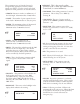
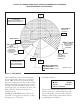
3.4 EDGE MOUNTING HOLES PASS LINE ADJUSTMENT CENTER LINE OF RAM C D 4. PROGRAMMING THE EDGE SERVO FEED SYSTEM IMPORTANT ! D Before turning the system on for the first time, verify that the main input voltage is correct (120 VAC single phase) and inspect all connections for tightness, shorts, etc. B PASS LINE E A TAP X 1” (25mm) DEEP BOLSTER STEP #1: TYPICAL MOUNTING ON GAP FRAME PRESS Press the amber ‘POWER ON’ push-button.
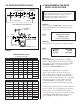
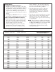
These parameters are set from the factory for average feeding applications and they seldom require any changes. The five screens and a brief explanation of the parameters are described below: CNTS/UNIT: This is the encoder scaling parameter used to define the number encoder counts/inch (or counts/millimeter). • TIME BASE: Time scaling parameter for various parameters. This is always set to ‘/SEC’ by entering ‘0’. • LENGTH: Distance in inches (or millimeters) of the feed length.
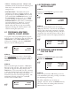
4.2 PROGRAM A NEW BATCH COUNT • FETime: Following error time. FETime is the maximum amount of time that the following error limit may be exceeded before executing an emergency stop. STEP #1 • SYSTEM RESET: This function clears all Position the ‘UNDERLINE’ type cursor under COUNT. Use the ◗ key. parameters to the factory default conditions. No program may be running, RESET must be active (press and hold the ‘POWER ON’ button), and the ‘PROG/RUN’ switch must be set to ‘PROG’ position.
LENGTH’ is reached, then either the ‘JOG FORWARD’, or ‘JOG REVERSE’ operator buttons will work. The ‘JOG REVERSE’ will not allow the strip to go backwards beyond the initial ‘FEED LENGTH’ starting point. The ‘JOG REVERSE’ The display should now show the new setting: ☞ LENGTH COUNT SPEED 00001.253 001000 0050/SEC operator button will function until the end of the ‘FEED LENGTH’ is reached. These (3) parameters may be changed when the running batch is stopped.
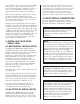
related error. Under ‘CYCLE STOP’ or ‘BATCH COMPLETE’ stopping, the output will turn off at the beginning of the ‘FEED CAM SIGNAL’. This 8. Jog the press down slowly observing when the longest pilot would engage the pilot hole in the material if the material were there. (Refer to Figure 4.) Note the press positional readout and put this setting into your Programmable Limit Switch (PLS) for the ‘PILOT RELEASE TURN ON’ setting. The ‘PILOT RELEASE TURN OFF’ setting should be 180. (See Figure 5.
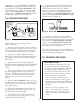
TYPICAL 180 DEGREE FEED ANGLE (FROM 260 DEGREES TO 80 DEGREES) WITH MECHANICAL PILOT RELEASE: TDC 0° FEED ADVANCE CAM 180° FEED ANGLE FEEDER STARTS FEEDING AT 260° AND MUST BE IN POSITION AT 80° FEED CAM “OFF” FEED MUST BE “IN POSITION” 80° FEED CAM “ON” 260° SAFETY ANGLE; PRESS RAM MUST STOP IN THIS ZONE IN EVENT OF A FEED ERROR ROLL CLOSING ZONE; FEED ROLLS MUST FULLY CLOSE IN THIS ZONE TO PREVENT ROLL SLIPPAGE AT START OF FEEDING 125° 235° ROLL OPENING ZONE FOR PILOT RELEASE (PNEUMATIC OR MECHAN
NOTES ABOUT "POSSIBLE PROBLEM TOOLING":* • A tight die, one that is not square, or has other did not "misfeed". The rolls were positioned properly, the strip did not keep up, causing the die to close and a miss-hit is produced. • The feed applies more power to a thin strip, causing the material to buckle somewhere between the feed and the die set. The feeder positioned the strip accurately, it just did not occur in the die set.
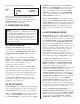
6. TROUBLESHOOTING GUIDE The chart that follows contains the most frequently encountered issues. SYMPTOM CAUSE or REMEDY No power indication when ‘POWER ON’ button is pressed • • • • • Check main power supply for proper voltage. Check supply fuses and circuit breakers. Verify that the main disconnect switch is on. Verify that the E-Stop is not engaged (E-Stop Loop closed.) Check bulb in ‘POWER ON’ push button. No display on power up • Check cabling connection between display and servo drive.
Some errors encountered with the Edge Servo Roll Feed may be diagnosed by the motion controller. These errors are typically displayed on the bottom line of the Operator Terminal Display. These errors are related to improper motion of the servomotor. These errors are listed below. These errors may be reset by either pushing ‘POWER ON’, which has a reset function, or by power-down and power-up. 6.
6.2 DRIVE MODULE DIAGNOSTICS Use the following table for Drive Module Diagnostics. LED Label LED Color LOGIC P/S Green Description • ‘OFF’ = No incoming AC (Alternating Current) or if AC is present then drive has internal power supply failure. • ‘ON’ = Power is present • During ‘POWER DOWN’, LED should turn off within approximately 1 second If not, shunt regulator is not functioning. Replace Drive. 1,2,3 Red • ‘OFF’ = No Fault 1 Red • ‘ON’ = Motor Over Temperature.
• The main drive belt should be checked periodically for tightness. It can be adjusted by loosening the two fasteners on the motor adjuster plate, applying downward pressure on the motor adapter plate, and retightening. ERRATIC MOTOR BEHAVIOR WILL BE EXPERIENCED IF THE DRIVE BELT IS LOOSE! • The Feeder’s electrical enclosure door is sealed to prevent oil and contaminants from entering inside. However, small gaps can be found around some sealing surfaces and faceplates.
EDGE MECHANICAL PARTS DIAGRAM 17135-01 PNEUMATIC PILOT RELEASE Item 1 2 3 4 4 4 DRAWING A17135-01 15 Description Solenoid Valve Solenoid Valve Solenoid Valve Solenoid Valve Cylinder, SRF-100 Cylinder, All Others Bracket Suppressor Suppressor Suppressor Part No.
WARNING Of vital importance to any successful program is the proper selection of guards and devices. However, there is no safety device that will bring "automatic" safety to your operation. This equipment offers various means of operating or controlling machines. The operator must not be in or near the point-of-operation of the machine, or the operating parts of any equipment installed on the machine, or bodily injury could result.