ULTRA EDGE SERVO ROLL FEED 2/14/2003 TABLE OF CONTENTS DESCRIPTION PAGE 1 INSTALLATION .............................................................................................................................................. 3 1.1 MECHANICAL INSTALLATION............................................................................................................ 3 1.2 ELECTRICAL INSTALLATION .............................................................................................................
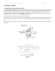
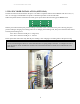
ULTRA EDGE SERVO ROLL FEED 2/14/2003 1 INSTALLATION 1.1 MECHANICAL INSTALLATION The Ultra Edge Servo Roll Feed is supplied with an adjustable mounting bracket. The feed should be securely mounted to the press frame. (A transition bracket is sometimes required in certain applications.) The feed should be centered, square, and perpendicular to the pass line of the press. It should be mounted at a height that will accommodate the appropriate die sets. The feed has a pass line height adjustment of ±1.
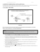
ULTRA EDGE SERVO ROLL FEED 2/14/2003 MOUNTING HOLES DIMENSIONS ENGLISH-INCHES DIMENSION A SRF-100 SRF-125 SRF-200 SRF-300 SRF- 400 / 500 / 600 1.18 1.97 1.97 1.97 1.97 B 1.97 3.15 3.94 3.94 3.94 C 3.94 6.30 7.87 7.87 7.87 D - - - TAP M14 M16 M16 M16 M16 E MIN. 2.2 2.4 2.4 2.4 2.4 PASS LINE ADJUSTMENT +2 -0.0 +2.4 +2.4 +2.4 +2.4 WIDTH OF 9.72 12.13 14.88 18.82 22.76 / 26.69 / 30.63 MTG. PLATE -0.0 5.91 -0.0 -0.0 -0.
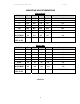
ULTRA EDGE SERVO ROLL FEED 2/14/2003 1.2 ELECTRICAL INSTALLATION The Ultra Edge Servo Roll Feed has been designed to make electrical connections quickly and easily. All that is required is a "clean" 110 VAC single-phase 15-ampere source that must be connected to the corresponding terminal blocks. It is recommended that #12 MTW (Machine Tool Wire) be used for the primary power supply input. The inputs and outputs to your press control (i.e.
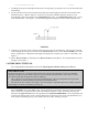
ULTRA EDGE SERVO ROLL FEED 2/14/2003 1.3 PLS ENCODER INSTALLATION (OPTIONAL) The PLS encoder must be mounted on the press so its shaft is coupled or belted to the crankshaft with one to one (1:1) ratio. It is strongly recommended to use plastic or aluminum sprockets on the encoder shaft. When all required electrical connections are made, power up the feed control and bring up the Status screen: Tool#1 Pos:182 Manual Mode 30 / Cont.
ULTRA EDGE SERVO ROLL FEED 2/14/2003 1.4 STRIP ENCODER INSTALLATION (OPTIONAL) The Strip Encoder comes pre-installed on the feed body and all it needs is proper electrical connections and air pressure of 80-100 PSI to the pressure regulator mounted on the front side of Strip Encoder Assembly 1.5 LOADING THE FEED FIGURE 3 Prior to this step, the electrical control must be powered up and all needed parameters are loaded. (Refer to the Ultra Edge Servo Feed Operating Manual.
ULTRA EDGE SERVO ROLL FEED 2/14/2003 7. Assuming that the press shut height and the tool are set up properly, jog the press one or two strokes without the feed working. 8. Jog the press down slowly observing when the longest pilot would engage the pilot hole in the material if the material were there. (Refer to Figure 4.) Note the press positional readout and put this setting into your Programmable Limit Switch (PLS) for the ‘Pilot Release On’ setting.
ULTRA EDGE SERVO ROLL FEED 2/14/2003 1.7 RUNNING THE FEED Put the Ultra Edge into “Auto” mode and press the Cycle Start button. The Ultra Edge Servo Roll Feed will now follow the press until the Operator stops it, counter, emergency stop, or feed error.
ULTRA EDGE SERVO ROLL FEED 2/14/2003 NOTES ABOUT ‘POSSIBLE PROBLEM TOOLING’: * o A tight die, one that is not square, or has other tooling problems, will cause significant difficulty and downtime. Accuracy in feeding is directly related to how easily the feeder can position the strip in the die. Binding, bad part ejection, or sticking parts may cause the material to "jam" in the die. o The Ultra Edge Servo Roll Feed will "try" to overcome the "jam-up" by applying more power to the rolls.
ULTRA EDGE SERVO ROLL FEED 2/14/2003 The SRF Pilot Release mechanism is pre-assembled, only needing outside air and electrical connections. For air connections, refer to Figure 6. The release is operated by applying the appropriate voltage signal to actuate the 3-way solenoid valve to open the feeder rolls. This power signal can come from a source such as a rotary cam switch.
ULTRA EDGE SERVO ROLL FEED 2/14/2003 3 MAINTENANCE The Ultra Edge Servo Roll Feed needs very little maintenance to keep the system operating at its optimum performance. o This precision equipment must be kept as clean as possible. This is especially important if large amounts of air suspended oil mists in combination with “dirty metals” are used. The resulting abrasive dust can attach itself to the feed rolls and other surfaces, leading to premature wear on many parts.
ULTRA EDGE SERVO ROLL FEED 2/14/2003 4 ROLL FEED PARTS LIST FIGURE 7 13
ULTRA EDGE SERVO ROLL FEED 2/14/2003 ITEM QTY DESCRIPTION 1 1 BEARING HOUSING - LEFT SIDE PLATE 2 1 BEARING HOUSING - RIGHT SIDE PLATE 3 1 PLATE- CASCADE MTG. 4 1 PLATE - FEED MTG.
ULTRA EDGE SERVO ROLL FEED 42 2 2/14/2003 CLAMP - GUIDE BAR 43 2 GUIDE ROLLER 44 4 SPACER - GUIDE ROLLER 45 2 NUT - T SLOT 46 3 ROLL - CASCADE, ENTRY 47 3 SHAFT - ROLL 48 10 BEARING - GUIDE & ENTRY ROLL 49 1 TRANSITION PLATE 50 1 ADJUSTMENT TAB 51 1 SCREW - HEX HD 52 1 NUT - HEX, JAM 53 1 KEY 22 mm x 5 mm x 110 mm 54 2 KEY 22 mm x 12 mm x 40 mm 55 1 STRIKER - RELEASE ACTUATOR 56 1 ARM - ADJUST 57 1 ARM - FIXED 58 1 BLOCK - MOUNTING 59 1 BRACKET - MOUNTING
ULTRA EDGE SERVO ROLL FEED 2/14/2003 5 OPTIONAL STRIP ENCODER PARTS LIST FIGURE 8 16
ULTRA EDGE SERVO ROLL FEED 2/14/2003 FIGURE 9 17
ULTRA EDGE SERVO ROLL FEED 2/14/2003 ITEM QTY DESCRIPTION 1 1 SLIDE 2 1 BASE 3 6 GIB ADJUSTMENT SCREW 4 1 ENCODER FLANGE 5 1 AIR REGULATOR 6 1 AIR CYLINDER 7 1 COUPLING 8 1 TOP PLATE 9 2 TOP PLATE SPACERS 10 1 T-NUT 11 1 MEASURING WHEEL 12 1 SUPPORT 13 1 SENSOR, CYLINDER DOWN 14 1 ENCODER 15 2 INDLER ROLL CLAMP 16 1 IDLER ROLL 17 2 NEEDLE BEARING 18 1 VALVE 19 2 SILENCER 20 1 WEAR PLATE 21 2 BRACKET EXTENSION 22 2 BRACKET UPRIGHT 23 1
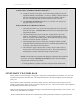
ULTRA EDGE SERVO ROLL FEED 2/14/2003 WARNING This equipment offers various means of operating or controlling machines. The operator must not be in or near the point-ofoperation of the machine, or the operating parts of any equipment installed on the machine, or bodily injury could result. The EMPLOYER must post adequate warning signs onto the machine with proper warnings for his machine and the specific application to which the machine and equipment are being applied.