/10/2003 ULTRA ADVANTAGE SERVO ROLL FEED TABLE OF CONTENTS DESCRIPTION PAGE 1 INTRODUCTION............................................................................................................................................... 3 2 THEORY OF OPERATION ............................................................................................................................. 3 2.1 MECHANICAL ASSEMBLY....................................................................................................
2/10/2003 ULTRA ADVANTAGE SERVO ROLL FEED RECEIVING INSPECTION BEFORE REMOVING UNIT FROM ITS PACKAGING, CHECK FOR VISUAL DAMAGE, ESPECIALLY IF CRATE, SKID, OR CARTON HAS BEEN DAMAGED IN TRANSIT. ANY DAMAGE CAUSED IN SHIPMENT SHOULD BE IMMEDIATELY REPORTED TO THE CARRIER. IF UNIT APPEARS IN SATISFACTORY CONDITION, REMOVE ALL PACKING AND WIPE RUST PREVENTIVE FROM ROLLERS WITH MILD SOLVENT.
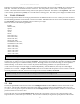
2/10/2003 ULTRA ADVANTAGE SERVO ROLL FEED ALL ULTRA ADVENTAGE SERVO ROLL FEED CONTROLS ARE CONVENIENTLY LOCATED ON THE FRONT SIDE OF THE ELECTRICAL ENCLOSURE 2.3 CONTROL/DEVICE DESCRIPTION Power On/Reset button Turns controller on, resets the servo drive. In Position indicator light, white Turns on when move is complete and motor is holding position. Cycle Start illuminated button, green Turns controller into “Auto” mode from “Manual” mode, starts cycling.
2/10/2003 ULTRA ADVANTAGE SERVO ROLL FEED Example: If a feed pitch/length of 11.138 inches is entered into the feeder, this will result in exactly one revolution of the feed rolls. The motor will accelerate and turn 10.24 turns. This will produce (10.24 x 8000 = 81,920) pulses of the encoder. The feeder will decelerate and stop, when 81,920 pulses are detected. The feeder is now in position. The result is an accurately positioned strip exactly 11.138 inches from its starting point.
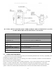
2/10/2003 ULTRA ADVANTAGE SERVO ROLL FEED shaft, constantly calculates (updates) its current position. The position of the press crankshaft is determined through the offset parameter, which is the position of the encoder shaft when the press is in its 0 degree position (TDC). Thus, at every point of the stroke, the servo drive knows where the crankshaft is. The servo drive controls six cams simultaneously, turning them on and off accordingly to the cam settings.
2/10/2003 ULTRA ADVANTAGE SERVO ROLL FEED 3 PROGRAMMING THE ULTRA ADVANTAGE SERVO ROLL FEED SYSTEM - OVERVIEW NOTE: Before attempting any programming, make sure that the “PROGRAMMING LOCKED / UNLOCKED” key switch is in the “Unlocked” position. NOTE: After power shutdown, WAIT for 10 seconds before powering up the Feed. Turn on the main power disconnect switch. This applies power to the control power supply. Press the green Power On push-button.
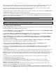
2/10/2003 ULTRA ADVANTAGE SERVO ROLL FEED 3.1 “OPER” KEY “OPER” key controls appearance of two screens: STATUS screen and OPERATOR screen. STATUS screen shows: Tool#1 Pos:182 Manual Mode 30 / Cont.Run Press a Mode Key • • • Active tool number. In case there is no active tool “No Tool!” message is displayed instead Current press position in degrees.
2/10/2003 ULTRA ADVANTAGE SERVO ROLL FEED Edit Tool#1 Arrow keys to scroll Press TOOLS to exit Activate Tool#1 Arrow keys to scroll Press TOOLS to exit Create Tool# Press TOOLS to exit NOTE: Tool number can contain up to seven digits. If “Activate Tool” operation is chosen, then the desired tool will be activated and message will be displayed for a few seconds: Tool Activated Display will show STATUS screen. Tool#1 Spd:384 Auto Mode 30 / Cont.
2/10/2003 ULTRA ADVANTAGE SERVO ROLL FEED Or Activate Tool# Arrow keys to scroll Press TOOLS to exit If “Edit Tool” or “Create New Tool” operation is chosen, then the next three (nine - with PLS option) screens will allow editing of the tool parameters. Position the cursor on desired line, using “↑” and “↓” keys , enter in the desired value, and press the “ENTER” key. Press “TOOLS” to open the next screen or “BKSP” – the previous. Tool#1 Length 60.000 Count Cont.
ULTRA ADVANTAGE SERVO ROLL FEED 2/10/2003 FeedCam On indicates the position of the press when the feed cam switch turns on and the feed starts feeding the material. FeedCam Off indicates the position of the press where the feeding must be completed. Otherwise, the servo drive will generate Synch Fault Signal, display the corresponding message in the screen, and stop feeding.
2/10/2003 ULTRA ADVANTAGE SERVO ROLL FEED Use SAVE to save the tool being edited. Press the “ENTER” key. Tool#1 Saved Use SAVE AS to create a new tool using the one being edited. Press the “ENTER” key, enter desired tool number, and press the “ENTER” key again. Save As Tool# Press TOOLS to Abort Save As #1234567 Tool#1234567 Saved The display will show the STATUS screen. Tool#1 Spd:384 Auto Mode 30 / Cont.
2/10/2003 ULTRA ADVANTAGE SERVO ROLL FEED Tool#1 Deleted Or Aborted! Display will show STATUS screen. Tool#1 Spd:384 Auto Mode 30 / Cont.Run Press a Mode Key NOTE: To exit tool editing at any time, press the “OPER” key. Changes will not be saved. 3.3 “SETUP” KEY “SETUP” key controls the appearance of setup screens. Seven screens contain parameters of the feed that are not changed often or never are changed. Press “SETUP” key three times to open the first screen.
2/10/2003 ULTRA ADVANTAGE SERVO ROLL FEED InPosition is a tolerance window around the final position. This is used to verify the feed index accuracy is within acceptable limits before continuing onto the next function. It is a numeric entry with a range of 0 to 100 inch. Normally set 0.02 inch. Priority is a parameter that selects whether the feeder indexes before the press starts “FBP” or the press starts before the feeder indexes “PBF”. Entering a “0” selects “PBF” mode and a “1” selects “FBP” mode.
2/10/2003 ULTRA ADVANTAGE SERVO ROLL FEED Back Length is used for Cut-to-Length application to protect the material against bending up by the blade. If any value is assigned for this parameter, the feed will move material back for the distance that equals Back Length when Reset Cam input is turned “On” by the blade bottom position sensor. The Back Length is compensated on the next move, so it has no affect on the Length parameter. It is a numeric entry, with a range of 0 to 1 inch.
2/10/2003 ULTRA ADVANTAGE SERVO ROLL FEED Release Ange is an angle of the feed release shaft rotation. It is proportional to the roll lifting distance. The rolls are open with no material at about 100, but some trial and error effort is normal to find the minimum lifting distance (minimum opening angle) for the certain application. It is a numeric entry with a range of 0 to 45degrees. Release Speed is a speed of the feed release shaft rotation. It is a numeric entry with a range of 0 to 9999 degree/sec.
2/10/2003 ULTRA ADVANTAGE SERVO ROLL FEED Tool Created Position cursor next to desired parameter, enter appropriate value, and press the “ENTER” key. Tool#1 Length 1.000 Count Cont.Run Press TOOLS for next Press “TOOLS” key to open next screen. Position cursor next to desired parameter, enter appropriate value, and press the “ENTER” key. Tool#1 Speed 72 Dwell 0 TOOLS-next BKSP-Prev Press “TOOLS” key to open next screen.
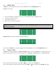
2/10/2003 ULTRA ADVANTAGE SERVO ROLL FEED Press “TOOLS” to open the next screen. Position cursor next to desired parameter; enter new value, and press “ENTER” key. Tool#1 Pos:354 Aux1 On 0 AuX1 Off 120 TOOLS-next BKSP-Prev Press “TOOLS” to open the next screen. Position cursor next to desired parameter, enter new value, and press “ENTER” key. Tool#1 Pos:354 Aux2 On 120 AuX2 Off 240 TOOLS-next BKSP-Prev Press “TOOLS” to open the next screen.
2/10/2003 ULTRA ADVANTAGE SERVO ROLL FEED Enter desired tool number or select it from the tool list using “↑” and “↓” keys and press the “ENTER” key again. Edit Tool# Arrow keys to scroll Press TOOLS to exit Edit Tool#1 Arrow keys to scroll Press TOOLS to exit Position cursor next to desired parameter, enter the new value, and press the “ENTER” key. Tool#1 Length 20.000 Count Cont.Run Press TOOLS for next Press “TOOLS” key to open next screen.
2/10/2003 ULTRA ADVANTAGE SERVO ROLL FEED Press “TOOLS” to open the next screen. Position cursor next to desired parameter, enter new value, and press “ENTER” key. Tool#1 Pos:354 PilotRel On 125 PilotRel Off 240 TOOLS-next BKSP-Prev Press “TOOLS” to open the next screen. Position cursor next to desired parameter; enter new value, and press “ENTER” key. Tool#1 Pos:354 Aux1 On 0 AuX1 Off 120 TOOLS-next BKSP-Prev Press “TOOLS” to open the next screen.
2/10/2003 ULTRA ADVANTAGE SERVO ROLL FEED Press “TOOLS” key, position the pointer next to EDIT TOOL command and press the “ENTER” key. Edit Tool < Activate Tool Create New Press TOOLS to Exit Enter desired tool number or select it from the tool list using “↑” and “↓” keys and press the “ENTER” key again. Edit Tool# Arrow keys to scroll Press TOOLS to exit Edit Tool#1 Arrow keys to scroll Press TOOLS to exit Position cursor next to desired parameter, enter new value, and press the “ENTER” key.
2/10/2003 ULTRA ADVANTAGE SERVO ROLL FEED Tool#1 Pos:354 ResetCam On 180 ResetCam Off 200 TOOLS-next BKSP-Prev Press “TOOLS” to open the next screen. Position cursor next to desired parameter, enter new value, and press “ENTER” key. Tool#1 Pos:354 PilotRel On 125 PilotRel Off 240 TOOLS-next BKSP-Prev Press “TOOLS” to open the next screen. Position cursor next to desired parameter; enter new value, and press “ENTER” key.
2/10/2003 ULTRA ADVANTAGE SERVO ROLL FEED Save as #5 Tool#5 Saved 4.3 HOW TO DELETE A TOOL NOTE: Make sure that the PROGRAMMING “LOCKED / UNLOCKED” key switch is in “Unlocked” position and OPERATOR screen is displayed. If the current screen is not OPERATOR one then press the “OPER” key to bring it up. Press “TOOLS” key, position the pointer next to EDIT TOOL command and press the “ENTER” key.
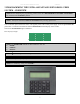
2/10/2003 ULTRA ADVANTAGE SERVO ROLL FEED Tool#1 Pos:354 FeedCam On 260 FeedCam Off 90 TOOLS-next BKSP-Prev Tool#1 Pos:354 ResetCam On 180 ResetCam Off 200 TOOLS-next BKSP-Prev Tool#1 Pos:354 PilotRel On 125 PilotRel Off 240 TOOLS-next BKSP-Prev Tool#1 Pos:354 Aux1 On 0 AuX1 Off 120 TOOLS-next BKSP-Prev Tool#1 Pos:354 Aux2 On 120 AuX2 Off 240 TOOLS-next BKSP-Prev Tool#1 Pos:354 Aux3 On 240 AuX3 Off 0 TOOLS-next BKSP-Prev Tool#1 Save Save as < TOOLS-next BKSP-Prev Tool#1 Delete Tool < TOOLS-next BKSP-Pre
2/10/2003 ULTRA ADVANTAGE SERVO ROLL FEED Tool#1 Deleted 4.4 HOW TO ACTIVATE A TOOL NOTE: Make sure that the PROGRAMMING “LOCKED / UNLOCKED” key switch is in “Unlocked” position and OPERATOR screen is displayed. If the current screen is not OPERATOR one then press the “OPER” key to bring it up. Press “TOOLS” key, position the pointer next to Activate tool command and press the “ENTER” key.
2/10/2003 ULTRA ADVANTAGE SERVO ROLL FEED 4.7 HOW TO EDIT LENGTH FROM OPERATOR SCREEN Locate the OPERATOR screen, position cursor next to the Length, enter new value, and press the “ENTER” key. Length 1.000 Count Cont.Run Length Adjustment Press OPER to exit 4.8 HOW TO EDIT COUNT FROM OPERATOR SCREEN Locate the OPERATOR screen, position cursor next to the Count, enter new value, and press the “ENTER” key. Enter “0” for continuous run. Length 1.000 Count Cont.
2/10/2003 ULTRA ADVANTAGE SERVO ROLL FEED Go back to Press offset parameter and change it to match PLS reading. PLS Counts/Rev Press Offset 1024 324 SETUP-Exit BKSP-Prev Recycle the power. Read PLS position from the status screen, it should be the same as the press’, “0” degrees. Tool# Pos: 0 Manual Mode 30 /Cont.Run Press a Mode Key At this point the press and PLS are synchronized and you can start setting cam On/Off parameters. 4.
2/10/2003 ULTRA ADVANTAGE SERVO ROLL FEED The Ultra Advantage Servo Roll Feed will now follow the press until it is stopped by the Operator, counter, emergency stop, or feed error. 5.3 “JTL” (JOG TO LENGTH) MODE “JTL” mode is used primarily during the threading of the strip through the die. This mode allows the Jog – To – “Feed Length” operations to be performed. While in the “JTL” mode, the strip may be moved using the remote Jog Pendant.
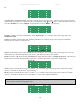
2/10/2003 ULTRA ADVANTAGE SERVO ROLL FEED Figure 6 SPEED PERFORMANCE CHART Velocity (in/sec) 2 Accel (in/sec ) Feed(in) 0.25 0.50 0.75 1.00 2.00 3.00 4.00 5.00 6.00 7.00 8.00 9.00 10.00 12.00 14.00 16.00 18.00 20.00 22.00 24.00 26.00 28.00 30.00 35.00 40.00 45.00 50.00 55.00 60.00 Velocity (in/sec) 2 Accel (in/sec ) Feed(in) 0.25 0.50 0.75 1.00 2.00 3.00 4.00 5.00 6.00 7.00 8.00 9.00 10.00 12.00 14.00 16.00 18.00 20.00 22.00 24.00 26.00 28.00 30.00 35.00 40.00 45.00 50.00 55.00 60.00 72.00 400.
2/10/2003 ULTRA ADVANTAGE SERVO ROLL FEED 5.5 TROUBLESHOOTING GUIDE The chart that follows contains the most frequently encountered issues. Symptom Cause or Remedy No power indication when Power On button is pressed 1. 2. 3. 4. 5. No display on power up 1. 2. 1. 2. Feed will not jog Power On indicator is lit. Feed will not operate. Feed will not accept new “Feed Length” or other parameters Inaccurate feeding Feed runs backwards Drive Fault Check the main power supply for proper voltage.
2/10/2003 ULTRA ADVANTAGE SERVO ROLL FEED 5.6 ERROR CODES Error Code Problem or Symptom 04 Motor Over Temperature 05 IPM Fault 09 Bus Under Voltage 10 Bus Over Voltage 11 Illegal Hall State 20 Motor Encoder State Error Possible Cause(s) Action/Solution Motor thermostat trips due to: High motor ambient temperature, and/or Excessive RMS torque. Bad encoder cable or connection. Motor cables shorted. Motor winding shorted internally. Ultra5000 Servo drive temperature too high.
2/10/2003 ULTRA ADVANTAGE SERVO ROLL FEED Error Code Problem or Symptom Possible Cause(s) Action/Solution 21 Auxiliary Encoder state Error The auxiliary encoder encountered an illegal transition. 22 Motor Thermal Protection Fault 23 IPM Thermal Protection Fault The internal filter protecting the motor from overheating has tripped. The internal filter protecting the IPM at slow speed has tripped. Use shielded cables with twisted pair wires.
2/10/2003 ULTRA ADVANTAGE SERVO ROLL FEED WARNING This equipment offers various means of operating or controlling machines. The operator must not be in or near the point-of-operation of the machine, or the operating parts of any equipment installed on the machine, or bodily injury could result. The EMPLOYER must post adequate warning signs onto the machine with proper warnings for his machine and the specific application to which the machine and equipment are being applied.