
User Manual
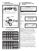

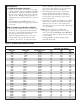

3.4 ADVANTAGE
MOUNTING HOLES
STEP #1:
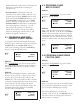
Turn on the main power disconnect switch. This
applies power to the control power supply. Press the
amber ‘
POWER ON’ push-button. The button will
illuminate and the data input display will be visible:
☞
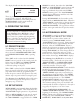
STEP #2:
Press any key on the terminal, the display will show:
☞
STEP #3:
The ‘POWER ON’ push-button has a ‘FAULT
RESET
’ function built into the button. Press the
‘
POWER ON’ button to clear the ‘ENCODER
FAULT
’ message at the bottom line of the display.
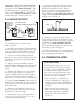
The feed may now be jogged forward by pressing
the ‘
JOG FORWARD’ button, or jogged in reverse
by pressing the ‘
JOG REVERSE’ button.
The Advantage Servo Roll Feed has six viewable
screens. Only the first operator screen (shown
above) will be operator editable/program-mable.
This screen displays the length, count, and speed
parameters. These parameters may only be changed
while the program is stopped (indicated by lack
of ‘
CYCLE START’ or set up light). The other
viewable screens are shown on the following page.
These five other screens will be viewable at all times,
but are "locked" out of programming via run/prog
switch located on the electrical panel inside the
electrical enclosure. The factory set parameter
values for the Advantage Servo Roll Feed are printed
on the operator panel below the operator terminal.
DIMENSION SRF-5 SRF-8 SRF-12 SRF-16/20/24/28/32/36
A 1.97 1.97 1.97 1.97
B 3.15 3.94 3.94 3.94
C 6.30 7.87 7.87 7.87
D – – – 5.91
TAP M14 M16 M16 M16
E MIN. 2.2 2.2 2.4 2.4
PASS LINE +2.4 +2.4 +2.4 +2.4
ADJUSTMENT -0.0 -0.0 -0.0 -0.0
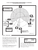
ADVANTAGE MOUNTING HOLES
for drawing 17147-03
DIMENSION SRF-5 SRF-8 SRF-12 SRF-16/20/24/28/32/36
A505050 50
B 80 100 100 100
C 160 200 200 200
D – – – 150
TAP M14 M16 M16 M16
E MIN. 56 56 60 60
PASS LINE +60 +60 +60 +60
ADJUSTMENT -00.0 -00.0 -00.0 -00.0
4
IMPORTANT !
Before turning the system on for the first time,
verify that the main input voltage is correct
(220 VAC single phase) and inspect all
connections for tightness, shorts, etc.
P/A INDUSTRIES
SERVO ROLL FEED
VERSION 1.00
HIT KEY TO CONT__
LENGTH 00008.000
COUNT 100000
SPEED 0062/SEC
ENCODER FAULT
ENGLISH
METRIC
EDGE SRF100-600
CENTER LINE OF RAM
C
L
D
C
D
B
E
A
TAP X 1” (25mm) DEEP
BOLSTER
BOLSTER
DRAWING 17147-03
ADJUSTABLE
CAM BAR
TYPICAL MOUNTING ON GAP FRAME PRESS
PASS LINE
ADJUSTMENT
PASS LINE
PASS LINE
E REF
A REF
Figure 2.
4. PROGRAMMING THE
ADVANTAGE SERVO FEED
SYSTEM