
User Manual
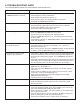

• This precision equipment must be kept as clean
as possible. This is especially important if large
amounts of air suspended oil mists in combination
with “dirty metals” are used. The resulting abrasive
dust can attach itself to the feed rolls and other
surfaces, leading to premature wear on many
parts.
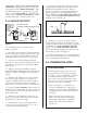
• The roll release system requires clean, dry air supply.
• Some bearings used on the feeder are fully sealed
and maintenance-free roller ball bearings. The
exceptions are provided with standard “zerk” type
grease fittings. They should be lubricated with a
good grade of high pressure bearing grease. The
frequency of lubrication will depend on the overall
usage of the system. A small “shot” once a day is a
good starting point. The cluster gear set should be
coated with a small amount of open gear grease.
• The main drive belt should be checked
periodically for tightness. It can be adjusted by
loosening the two fasteners on the motor adjuster
plate, applying downward pressure on the
14
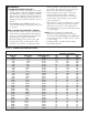
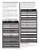
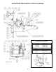
1 1 BEARING HOUSING - LEFT SIDE PLATE
2 1 BEARING HOUSING - RIGHT SIDE PLATE
3 1 PLATE- CASCADE MTG.
4 1 PLATE - FEED MTG.
5 1 PLATE - EXIT
6 1 PLATE - MATERIAL HOLD DOWN
7 1 BRACKET - UPPER ROLL, LEFT
8 1 BRACKET - UPPER ROLL, RIGHT
9 1 PLATE - UPPER ROLL
10 1 GUARD - ENTRY
11 1 ROLL - LOWER
12 2 DUST SHIELD - LOWER
13 1 SPACER - LOWER
14 2 BEARING - LOWER
15 1 GEAR - LOWER
16 1 ROLL - UPPER
17 2 DUST SHIELD - UPPER
18 2 RETAINING RING
19 2 BEARING - UPPER
20 1 GEAR - UPPER
21 1 SHAFT - THICKNESS ADJUSTMENT
22 1 LEVER - THICKNESS ADJUSTMENT
23 1 CAM ECCENTRIC BUSHING
24 1 BUSHING - TAPER LOCK - INNER
25 1 BUSHING - TAPER LOCK - OUTER
26 1 SHAFT - ROLL RELEASE
27 2 BEARING, NEEDLE
28 2 WEAR PAD
29 1 RELEASE LEVER - MANUAL
30 1 RELEASE LEVER - MECHANICAL
31 1 BEARING - ROLL RELEASE
32 1 SPACER - RELEASE BEARING
33 2 RETAINER, SPRING ROD
ITEM QTY DESCRIPTION
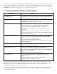
motor adapter plate, and retightening.
ERRATIC MOTOR BEHAVIOR WILL BE
EXPERIENCED IF THE DRIVE BELT IS
LOOSE!
• All fasteners should be checked for tightness at
regular intervals. The electrical system also requires
very little maintenance. Keep the enclosure clean
and replace any burned indicator bulbs. Do not
expose the electrical enclosure to constant high
temperatures. Possible system failure could result.
• The Feeder’s electrical enclosure door is sealed
to prevent oil and contaminants from entering
inside. However, small gaps can be found around
some sealing surfaces and faceplates. It is a good
idea, therefore, to keep the console free of
stamping oils and fluids, which could "seep into"
the enclosure. Most often, these oils are carried by
the operator’s hands or by air mist lubrication etc.
• All of the above guidelines should be added to
your existing pressroom Preventive Maintenance
(PM) Program.
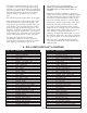
34 2 ROD, ROLL TENSION
35 2 SPRING, ROLL TENSION
36 1 SET SCREW M6 X 16
37 2 BRACKET - CASCADE
38 1 BLOCK - CASCADE MTG., LEFT
39 1 BLOCK - CASCADE MTG., RIGHT
40 1 PLATE - ENTRY
41 2 BAR - GUIDE ROLLER
42 2 CLAMP - GUIDE BAR
43 2 GUIDE ROLLER
44 4 SPACER - GUIDE ROLLER
45 2 NUT - T SLOT
46 3 ROLL - CASCADE, ENTRY
47 3 SHAFT - ROLL
48 10 BEARING - GUIDE & ENTRY ROLL
49 1 TRANSITION PLATE
50 1 ADJUSTMENT TAB
51 1 SCREW - HEX HD
52 1 NUT - HEX, JAM
53 1 KEY 22mm x 5mm x 110mm
54 2 KEY 22mm x 12mm x 40mm
55 1 STRIKER - RELEASE ACTUATOR
56 1 ARM - ADJUST
57 1 ARM - FIXED
58 1 BLOCK - MOUNTING
59 1 BRACKET - MOUNTING
60 1 NUT, STRIKER ADJUST
63 1 KEY 7mm SQ x 35mm
64 1 KEY 5mm SQ x 15mm
65 4 GREASE FITTING
67 4 NUT, M14, ROLL TENSION
69 2 HANDLE, WIDTH GUIDE ADJUSTMENT
70 1 HANDLE, THICKNESS ADJUSTMENT
71 6 NUT, HEX
ITEM QTY DESCRIPTION
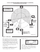
8. ROLL FEED PARTS LIST & DIAGRAM