
User's Manual

P.G. TM0040AE
3-4
3.3 OPERATING INSTRUCTIONS
The A289 dual band bidirectional amplifier has no external controls. When powered the
unit will amplify signals in each band and in each direction.
When the green light is on, bias conditions of active devices in all the RF paths are within
specifications and the downlink power in each band is above the minimum preset limit. The
red FAULT light goes on whenever a monitored active device in the RF paths has failed or
the downlink output power is too low. Corrective action is to check if the input power in
each band is correct and then to check the fault conditions as indicated below.
3.4 FAULT CONDITIONS
If the FAULT light is illuminated it indicates that one of the following conditions have
occurred. Four LEDs on the side of the unit show the status of the RF and DC bias alarms
and indicate the source of the fault conditions.
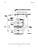
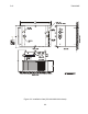
3.4.1 Low RF power (“PWR” LED on)
- Check the level of RF power out of the amplifier
by connecting a meter or spectrum analyzer to the Test Port J3. The actual level is higher
than the measured level by 30 dB at cellular and 24 dB at PCS frequencies. If the RF fault
option is enabled a fault will occur if the RF power in either band falls below approximately
+5 dBm.
By measuring the RF input power at J4 in each band the correct functioning of the amplifier
can be checked. The gain should be approximately 20 dB minus the inserted attenuation.
3.4.2 DC Bias Change (“BIAS” LED on)
- A DC bias alarm indicates a fault in the
amplifier for the particular frequency band indicated. This condition mandates replacement
of the amplifier except as noted below.
NOTE:
The cellular uplink amplifier will show a DC bias alarm if the amplifier is
driven into saturation by excessive RF power levels. A true DC bias fault will
persist when RF carriers have been reduced in level.