
User's Manual

P.G. TM0040AE
4-2
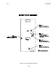
4.2 ATTENUATION (AC AND AP)
The A289 has a nominal overall gain of 20 dB in both the cellular and PCS frequency
bands, but this gain may be reduced by built-in attenuators included in each frequency
band. The attenuators are installed on the uplink side of the amplifier and hence do not
have significant impact on the uplink system noise figure.
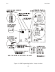
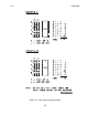
The attenuator for each band is set for values from 0 to 15 dB by four jumpers in a binary
sequence. Setting the jumpers to the “IN” position inserts, 1, 2, 4 or 8 dB attenuation in the
circuit for that band. Refer to the label attached to the inside of the cover for an enlarged
view of these jumpers and their setting positions.
NOTE
: The jumpers must be set to either the IN or OUT positions for correct attenuator
operation. Do not leave open. If the optional AUTOSET control board is fitted,
see Appendix A for further information.
4.3 FAULT OPTIONS (F)
The block of four jumpers for the fault options allows disabling of each of four tests by
removing the appropriate jumper.
The jumpers to monitor downlink RF power are labelled CRF for the cellular band and PRF
for the PCS band.
The jumpers to disable amplifier bias current monitoring are labelled CB for the cellular
amplifier and PB for the PCS amplifier.