
User's Manual

P. G. TM0060
2-1
SECTION 2. THEORY OF OPERATION
2.0 GENERAL
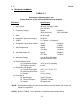
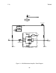
As explained in Section 1, the A238 is a bidirectional amplifier, which provides 20dB of
gain in the PCS wireless transmit and receive bands. The block diagram of the A238 is
shown in Figure 2-1.
2.1 DESCRIPTION
2.1.1 The unit is composed of band pass diplexers, amplifier stages and alarm and
voltage regulation circuits.
2.1.2 The bias conditions of amplifier stages are monitored. If the bias changes outside
certain limits a fault condition is indicated. The downlink RF output power is also
monitored. If the power drops below established limits a FAULT condition is indicated.
When a FAULT condition occurs the unit transmits the unit identification (or "Fault Code")
by two level amplitude modulation of a low frequency carrier placed on the cable center
conductor. The signal is transmitted as a short burst repeated at approximately 80
second intervals while the fault condition persists. The fault code can be reprogrammed
as described in Section 3.2. While a NORMAL condition exists the amplifier transmits an
OK code at intervals of approximately 80 minutes.
2.1.3 The voltage regulators take 24 - 28 VDC input and provide 20 VDC and 12 VDC
outputs. A zener diode provides transient protection against voltage spikes on the cable.
2.1.4 The unit requires external DC power to be supplied through the 5-pin DIN
receptacle. The unit should be powered locally by the PS293 external power source.
The local power source is isolated from J1 and J2.
The unit provides DC continuity from J1 to J2 to allow downstream cable powered
amplifiers to receive their power from upstream power sources such as the PS212 and
PS213. In addition, status signals from downstream cable powered amplifiers are passed
through the amplifier from J1 to J2.