
User's Manual

P. G. TM0060
1-2
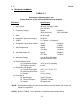
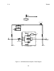
1.2 TECHNICAL SUMMARY
TABLE 1-1.
Performance Characteristics and
Salient Features of the A238 PCS Bidirectional Amplifier
Parameter Specification
1. Input Power: 24 to 28 VDC @ 2 A Max
(use PS 293)
2. Frequency Range*: Uplink: Downlink:
1850-1910 MHz 1930-1990 MHz
3. Gain: 20 dB ±2 dB
4. Impedance (Input and Output): 50 Ohms
5. VSWR: 2:1 Typical, 3:1 Maximum
6. Composite output power rating**: Uplink: Downlink:
+4dBm +24dBm
7. 1dB Compression: Uplink: Downlink:
+12 dBm +33 dBm
8. 3rd Order Output IP: Uplink: Downlink:
+27 dBm +45 dBm
9. Attenuator Range 0 to 15 dB (1 dB steps)
(optional Autoset PCB)
10. Environmental Limits:
(a) Temperature Range: -30°C to 60°C operating
(b) Relative Humidity: to 90%
11. Dimension and Weight:
(a) Overall Dimensions: 9.8” L x 6.7” W x 6.7” H
(b) Mounting Hole Dims: 9” x 5”
(c) Weight: 5.8 lb (2.6 kg)
12. Connectors:
RF Input/Output: Type N Female
RF Test Input/Output: Type BNC Female
DC supply: DC power jack
*NOTE: Specifications apply only across the customer’s actual bands, not across the
whole PCS spectrum.
**NOTE: Refer to TABLE 1-2 for definition of composite output power rating.