
User's Manual


P. G. TM0060
1-1
SECTION 1. GENERAL INFORMATION
1.1 INTRODUCTION
1.1.1 Scope of Manual - This manual is intended to familiarize service personnel
working on the PCS Bidirectional Amplifier A238 with all pertinent aspects of the
amplifier. Included in this manual are a brief physical description, a technical summary,
installation information and operating data.
1.1.2 Purpose of Equipment - The A238 amplifier is used as a drop-in booster for
PCS signals. It will simultaneously amplify signals in the PCS transmit band in one
direction and the PCS receive band in the opposite direction. A typical use of the A238
is to provide wireless phone coverage in underground installations.
1.1.3 Physical Description - The bidirectional amplifier, shown in Figure 3-1, is
designed to be mounted on a flat vertical surface. The unit has two N connectors for
external electrical connection and two BNC test ports to check RF signals. Color coded
indicators provide visual display of the unit's operating status.
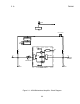
1.1.4 Electrical Description - The bidirectional amplifier provides approximately 20
dB of gain for signals in the 1850 - 1910 MHz band in the direction of J1 to J2 (antenna
to base) and the same amount of gain for signals in the 1930 - 1990 MHz band in the
opposite direction (J2 to J1).
1.1.4.1 The unit is locally powered through a 5-pin DIN receptacle. The P.G.
Electronics PS293 power source should be used to power the unit. The unit provides
DC continuity from J1 to J2 to allow powering of downstream amplifiers from upstream
power sources such as PS212 and PS213. Local power is isolated from J1 and J2.
1.1.4.2 The unit monitors bias conditions of active devices in the RF path and monitors
downlink power. If one of these devices draws more or less than a predetermined limit,
or if the RF downlink power is low then the FAULT indicator will go on. Under normal
operating condition only the green NORMAL indicator will be on.
1.1.4.3 If a FAULT condition is detected the unit transmits a low frequency identification
code along the cable center conductor. The burst transmission is repeated at
approximately 80 second intervals while a fault condition exists.
1.1.4.4 If a NORMAL condition exists in the amplifier a low frequency OK identification
code will be transmitted on the cable at intervals of approximately 80 minutes.
1.1.4.5 The unit has an adjustable attenuator to allow operation at reduced gain. The
attenuator is settable in 1 dB steps up to 15 dB either manually or by using an optional
AUTOSET control board.