
User's Manual


P. G. TM0060
3-2
3.2 INSTALLATION
The bidirectional amplifier is designed for mounting on a flat vertical surface The unit is
mounted with the indicator side down for adequate air circulation. Proceed as follows:
1. Locate a suitable mounting location, allow a clearance of at least 5 inches (13 cm)
to route mating cable and connectors to the unit. Drill four pilot holes on 9 x 5 inch
centers for No.10 fasteners.
2. Mount the amplifier ensuring there is good air circulation around the amplifier.
3. Connect J2, "BASE" to the cable leading to the base transmitter.
4. Connect J1, "ANTENNA" to the cable leading to the distribution antenna(s).
If it is known that the programming has been correctly preset as required by the
system plan then this completes the installation. It is recommended the alarm
code, alarm option settings and attenuation settings for each amplifier be recorded
on the system "as-built" drawing. Otherwise perform the steps below as required.
5. If DC continuity, attenuation, alarm options or alarm code must be changed,
remove the cover plate from the amplifier to provide access to the programming
jumpers.
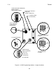
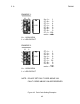
NOTE: Section 4.0 of this manual describes programming details. For
convenience a reduced size copy of diagram Figure 4-1 is provided on the inside
of the amplifier cover as a reference.
6. If the unit is NOT required to pass DC or downstream amplifier status signals, then
it is recommended that the "DCJ1 DCJ2" be removed to provide DC isolation at
J1. See Section 4.1.
7. If certain fault alarms should be disabled then reprogram the appropriate jumpers
as described in Section 4.3.
8. If it is required to change the factory set alarm code then program the appropriate
jumpers as described in Section 4.6.
9. If the attenuator must be set then refer to section 4.2. If the optional AUTOSET
control board is fitted, skip this step.
10. Replace the amplifier cover. NOTE: It must be correctly oriented to fit properly.
This completes the installation.