
User's Manual

P. G. TM0060
2-4
2.2.3 Fault Conditions - The fault circuitry monitors two separate parameters in the
unit. These are (a) the bias conditions of active devices in the amplifier and (b) the
presence of downlink RF output power. Each function can be disabled as described in
Section 4, if the unit is being used in a restricted operational mode.
The DC current monitoring triggers a fault condition if the DC bias deviates outside
predetermined high or low limits.
The downlink RF output power is monitored by a detector and a FAULT condition is
triggered if the level drops below a nominal level of + 5 dBm. If the amplifier is to be
installed at a point in the system where the output power may be less than +7 dBm then
the RF monitor circuit should be disabled as described in Section 4 herein.
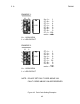
The local fault indicators indicate specific faults as follows:
PCS
BIAS Bias fault in the PCS amplifier
PWR Low downlink RF power from the PCS amplifier
NOTE: There is a certain situation in which the red “FAULT” indicator will be on even
though none of the “BIAS” or “PWR” indicators are on. This situation occurs
when the unit is receiving local power and downlink RF powers are normal but
the cable power is not present. This indicates that the cable power source
located upstream has been switched off or has shut down.