
Installation Manual

BX-SVN-JAYFLTR101-1A-EN 3
Installer's Guide
Installation Instructions
These instructions are organized for an easy step-by
step procedure.
NOTE: These instructions do not purport to cover
all variations in system nor to provide for every
possible contingency to be met in connection with the
installation. Should further information be desired or
should particular problems arise which are not covered
sufficiently for the purchaser’s purposes, the matter
should be referred to the manufacturer.
1. Disconnect all power sources to the Oxbox
packaged unit.
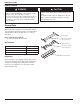
2. Remove the filter access panel. Set panel aside for
later re-installation. See Figure 2.
Figure 2. Panel Removal
Filter access panel
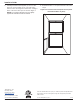
3. The filter racks fit tightly inside the cabinet. Use care
not to damage unit insulation when installing filter
racks.
4. Place the bottom filter rack into the cabinet and slide
up against the unit panel. The bottom filter rack will
rest directly on the base. Using screws provided,
screw through the pre-punched holes in the back
flange of the filter rack and into unit panel. See
Figure 3.
5. To make sure the center and top filter rack are
aligned with the bottom rack, use a marker and draw
a vertical line on the unit insulation, starting from
the edge of the bottom rack all the way up to the top
of the unit. Draw this line on both the left and right
sides of the bottom rack. See Figure 3.
6. Measure up 20 ¼” vertically from the bottom rack
to locate the center filter rack. The rack can be held
in place by itself when squeezed in place. Using
screws provided, screw through the pre-punched
holes in the center rack and into the unit on both
sides. See Figure 3.
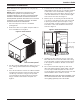
Figure 3. Filter Rack Locations
Top Filter Rack
Center Filter
Rack
Bottom Filter Rack
16” x 20” Filter
Side supply
air opening
Screw
Side return
air opening
20-1/4”
20” x 20” Filter
7. Install the top filter rack at the very top of the unit,
inline with the bottom and center filter racks. Using
screws provided, screw through pre-punched holes
in the top filter rack and into the unit on both sides.
See figure 3.
8. The screws installed through the top and center
filter racks and through the outside panel of the unit,
are now exposed and sharp. One at a time, these
screws should be removed from the inside of the unit
and reinstalled from the outside of the unit.
NOTE: After the screws have been reinstalled, cover
the screw threads with caulk. This will minimize the
risk of getting injured by one of the screws.