
J962V Installation Manual

24
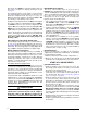
NOTE: Turning the adjusting screw clockwise
increases the pressure and counterclockwise
reduces the pressure.
d. Reinstall plastic cap after adjustment is complete.
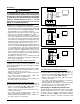
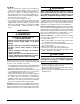
Verifying & Adjusting Temperature Rise
Confirm the temperature rise through the furnace is
within the limits specified on the furnace rating plate. Any
temperature rise outside the specified limits could result
in premature failure of the heat exchanger.
1. Place thermometers in the return and supply air stream
as close to the furnace as possible. To avoid false
readings, the thermometer on the supply air side must be
shielded from direct radiation from the heat exchanger.
2. Adjust all registers and duct dampers to the desired
position and run the furnace for 10 to 15 minutes in
high fire before taking any temperature readings. The
temperature rise is the difference between the supply
and return air temperatures.
For typical duct systems, the temperature rise will fall
within the limits specified on the rating plate with the
blower speed at the factory recommended setting. If
the measured temperature rise is outside the specified
limits, it may be necessary to change the speed of the
blower. NOTE: Lowering the blower speed increases the
temperature rise and a higher blower speed will decrease
the temperature rise.
The furnace is equipped with a multi-speed motor. Heating
and cooling speed selection is made by moving the
switches on the integrated control located in the furnace.
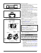
Verifying Burner Operation
CAUTION:
The door over the burners may only be open
for inspection purposes only. The door must be
installed during unattended operation.
1. Remove the burner compartment door.
2. Set the thermostat above room temperature and observe
the ignition sequence. The burner flame should carry
over immediately between all burners without lifting off,
curling, or floating. The flames should be blue, without
yellow tips.
3. After validating flame characteristics, change thermostat
setting to below room temperature.
4. Verify burner flame is completely extinguished.
5. Replace the burner compartment door.
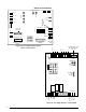
OPERATING SEQUENCE
The operating sequences for the heating, cooling, and
fan modes are described below. Refer to the field and
furnace wiring diagrams: Figure 16 (page 20), Figure 17
(page 21)
, Figure 18 (page 21), Figure 19 (page 21) &
Figure 26 (page 31).
Heating Cycle
1. The thermostat calls for heat by energizing the W1
terminal with 24VAC.
2. The control checks to see the pressure switch is open.
If the switch is closed, the furnace will shut down for 5
minutes before retrying
3. If the pressure switch is open, the control energizes the
inducer motor and waits for the pressure switch to close.
The pressure switch must close within 12 seconds.
4. The control runs the inducer for a 30 second pre-purge
time.
5. The control energizes the igniter output for the
appropriate adaptive warm-up time limit.
6. The furnace always ignites the burners in high fire. If
the call for heat is for low rate, the furnace will move
down to low fire after the flames stabilize.
7. If the flame is proved and ignites the gas, the control
de-energizes the igniter. The gas valve and inducer
remains energized. The control goes to blower on delay.
8. The control energizes the blower on the selected HEAT
speed 22 seconds after the gas valve opened. The gas
valve and inducer remain energized.
9. If there is a call for high fire, the gas valve moves to the
high fire position and the blower speeds are increased.
The furnace will remain in high fire until the demand
for heat is satisfied.
10. If autostaging is enabled (single stage thermostat) the
demand for heat has lasted more than the selected
time, the furnace automatically moves up to high fire.
Autostage time is ON (10 minutes) or OFF, depending
on the Jumper (P7) setting on the furnace control board.
11. When the thermostat demand for heat is satisfied, the
control de-energizes the gas valve. The inducer output
remains on for a 30 second post-purge period.
12. The circulating air blower will continue to run for the
selected Blower Off Delay(P5). This may be 60, 90,
or 120 seconds depending on the jumper setting on
the furnace control board.
Cooling Cycle
1. The thermostat calls for cooling by energizing the Y /
Y2 or Y1 terminal with 24VAC.
2. The control energizes the blower in the cooling speed
and sends 24VAC to the contactor in the condensing
unit.
3. When the thermostat removes the call for cooling, the
contactor in the outdoor condensing unit is de-energized
and the control continues to run the fan for a period of
60 seconds.