
J962V Installation Manual

23
Start-up Procedures
Do not perform these steps until all of the checks in the
previous steps have been completed:
1. Set the thermostat to the lowest setting.
2. Turn off all electrical power to the furnace.
3. Follow the Operating Instructions on the furnace label.
4. Set the thermostat above room temperature and verify
the Operating Sequence. See page 24.
5. After 5 minutes of operation, set the thermostat below
room temperature and verify steps 11 & 12 of the
Operating Sequence.
Verifying & Adjusting Input Rate
The input rate must be verified for each installation to
prevent over-firing of the furnace. NOTE: The input rate
must not exceed the rate shown on the furnace rating plate.
At altitudes above 2,000 feet, it must not exceed that on
the rating plate less 4% for each 1,000 feet. To determine
the exact input rate, perform the following procedures:
1. Shut off all other gas fired appliances.
2. Start and run the furnace in high fire for at least 3
minutes.
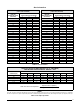
3. Measure the time (in seconds) required for the gas
meter to complete one revolution.
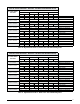
4. Convert the time per revolution to cubic feet of gas per
hour using
Table 6 (page 27).
5. Multiply the gas flow rate in cubic feet per hr by the
heating value of the gas in Btu per cubic ft to obtain
the input rate in Btuh. See example below.
EXAMPLE:
• Time for 1 revolution of a gas meter with a 1 cubic
ft dial = 40 seconds.
• From Table 6 read 90 cubic ft gas per hr.
• Local heating value of the gas (obtained from gas
supplier) = 1,040 Btu per cubic ft.
• Input rate = 1,040 x 90 = 93,600 Btuh.
6. The manifold pressure must be set to the appropriate
value for each installation by a qualified installer, service
agency or the gas supplier.
WARNING:
Do not attempt to drill the gas orifices. Use only
factory supplied orifices. Improperly drilled
orifices may cause fire, explosion, carbon
monoxide poisoning, personal injury or death.
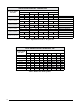
a. Remove plastic cap from pressure regulator.
b. Obtain the manifold pressure setting required for
this installation by referring to Table 8 (page 28)
for Propane or Table 10 & Table 11 (page 29) for
Natural Gas.
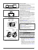
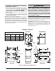
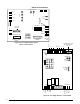
c. Using an Allen wrench, turn the the LO Input
Adjusting Screw on the LO side of the regulator
to adjust the reduced input setting or turn the HI
Input Adjusting Screw on the side of the regulator to
adjust the full input setting. See Figure 22 (page 23).
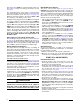
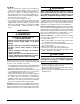
Figure 21. DEHUM Wiring Configuration
without Humidistat
DEHUM
R
BLOWER CONTROL
C
O (B)
ADDED RELAY
(Normally Open)
Figure 22. HI & LO Input Adjusting Screws
IN
ON
OFF
Inlet
Pressure
Ta p
Inlet
Pressure
Ta p
Manifold
Pressure
Ta p
Manifold
Pressure
Ta p
2-STAGE GAS VALVES
Model VR8205Q2381
Model VR9205Q1028
ON / OFF
Knob
ON / OFF
Switch
HI Input
Adjusting
Screw
Lo Input
Adjusting
Screw
HI Input
Adjusting
Screw
Lo Input
Adjusting
Screw
DHUM
R
R
DHUM
HUMIDIS
TAT
MOTOR
CONTROL BO
ARD
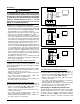
Figure 20. DEHUM Wiring Configuration
with Humidistat