
J962V Installation Manual

18
• Some local regulations require the installation of a
manual main shut-off valve and ground joint union
external to the furnace. The shut-off valve should
be readily accessible for service and/or emergency
use. Consult the local utility or gas supplier for
additional requirements regarding placement of the
manual main gas shut-off. See Figure 15 (page 18).
• Per ANSI 21.47, A 1/8-inch NPT plugged tapping,
accessible for test gauge connection, must be
installed immediately upstream of the gas supply
connection to the furnace external to the cabinet. If
local codes allow the use of a flexible gas appliance
connector, always use a new listed connector. Do
not use a connector that has previously serviced
another gas appliance.
• Gas piping must never run in or through air ducts,
chimneys, gas vents, or elevator shafts.
• Compounds used on threaded joints of gas piping
must be resistant to the actions of liquefied
petroleum gases.
• The main gas valve and main power disconnect to
the furnace must be properly labeled by the installer
in case emergency shutdown is required.
• Flexible gas connectors are not recommended for
this type of furnace but may be used if allowed by
local jurisdiction. Only new flexible connectors may
be used. Do not reuse old flexible gas connectors.
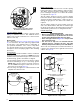
• A drip leg should be installed in the vertical pipe
run to the unit. See Figure 15.
Table 7 (page 27) lists gas flow capacities for standard
pipe sizes as a function of length in typical applications
based on nominal pressure drop in the line.
NOTE: The ‘A’ width furnace can only be installed with
right side gas entry. ‘B’, ‘C’, & ‘D’ width furnaces may be
installed for either left or right side gas entry.
When connecting the gas supply, provide clearance
between the gas supply line and the entry hole in the
furnace casing to avoid unwanted noise and/or damage to
the furnace. Typical gas hookups are shown in
Figure 15.
Leak Check
WARNING:
FIRE OR EXPLOSION HAZARD
Failure to follow safety warnings exactly could
result in serious injury, death or property
damage.
Never test for gas leaks with an open flame.
Use a commercially available soap solution
made specifically for the detection of leaks
to check all connections. A fire or explosion
may result causing property damage, personal
injury or loss of life.
After the gas piping to the furnace is complete, all
connections must be tested for gas leaks. This includes
pipe connections at the main gas valve, emergency
shutoff valve and flexible gas connectors (if applicable).
The soap and water solution can be applied on each
joint or union using a small paintbrush. If any bubbling is
observed, the connection is not sealed adequately and
must be retightened. Repeat the tightening and soap
check process until bubbling ceases.
IMPORTANT NOTE
When pressure testing gas supply lines at pressures
greater than 1/2 psig (14 inch W.C.), the gas supply
piping system must be disconnected from the furnace
to prevent damage to the gas control valve. If the test
pressure is less than or equal to 1/2 psig (14 inch
W.C.), close the manual shut-off valve.
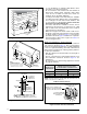
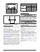
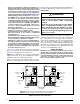
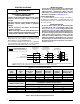
Figure 15. Typical Gas Connections
Right Side Entry
Left Side Entry
See
Note “B”
See
Note “B”
See
Note “A”
See
Note “A”
Plug
Shut - Off
Valve
Dripleg
Ground
Joint
Union
Pipe
Nipple
Elbow
Shut - Of
f
Valve
Dripleg
Ground
Joint
Union
Manifold
Burner
Assembly
Pipe
Nipple
Elbow
Gas
Valve
Gas
Valve
Manifold
NOTE A: Consult local codes for Shut-Off Valve location requirements
NOTE B: Inducer assembly omitted for clarity of pipe installation.