
J962V Installation Manual

17
The 1/2” x 3/4” hose barb can be used to route the
condensate drain to the outside of the cabinet. It must
be installed from inside the cabinet with the threaded
end inserted thru the 1 1/16” hole. See Figure 23 (page
26)
for hole location The condensate drain should be
connected to the barbed end. Attach 1” PVC drain line
to the threaded end.
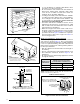
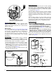
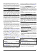
Typical Orientation
1. Install the PVC Tee vertically on the 2” vent pipe that is
extending out the side of the cabinet. Permanently bond
them together using appropriate primer and cement.
Refer to the typical orientation shown in Figure 14.
2. Install the reducer or PVC trap (if supplied) on the bottom
end of the PVC Tee. Permanently bond them together
using appropriate primer and cement.
3. Install the 1/2” x 1/2” hose barb on the 2” PVC reducer.
NOTE: Do not over tighten! Use an adequate amount of
Teflon tape on the threads. Do not use liquid sealants.
4. Verify all connections and joints for tight fit and proper
alignment with other vent pipes.
Alternate Orientation
1. Install the 2” PVC Tee horizontally on the 2” vent pipe
that is extending out the side of the cabinet. Permanently
bond them together using appropriate primer and
cement. Refer to the alternate orientation shown in
Figure 14.
2. Install the 2” PVC Elbow on the end of the 2” PVC Tee.
Permanently bond them together using appropriate
primer and cement.
3. Install the reducer or PVC trap (if supplied) on the bottom
end of the PVC Tee. Permanently bond them together
using appropriate primer and cement.
4. Install the 1/2” x 1/2” hose barb on the 2” PVC reducer.
NOTE: Do not over tighten! Use an adequate amount of
Teflon tape on the threads. Do not use liquid sealants.
5. Verify all connections and joints for tight fit and proper
alignment with other vent pipes
Condensate Drain Lines
IMPORTANT NOTE
If the furnace is installed in an area where temperatures
fall below freezing, special precautions must be made
for insulating condensate drain lines that drain to the
outdoors. If condensate freezes in the lines, this will
cause improper operation or damage to the furnace. It
is recommended that all drain lines on the outside of
the residence be wrapped with an industry approved
insulation or material allowed by local code.
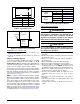
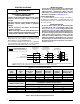
The placement of the condensate drain lines will depend
on the configuration selected in Table 4, (page 15). The
drain lines can be routed out the left or right side of the
furnace, but must maintain a downward slope to ensure
proper condensate drainage.
The J-trap may need to be rotated to the side that matches
your setup in Figure 27 (page 33). To rotate the J-trap,
loosen the clamp on the drain tube, rotate the J-trap to
either side, and retighten the clamp.
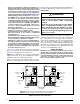
THREE GENERAL RULES APPLY:
• Each condensate drain line within the furnace must
be separately trapped using a J-Trap or field supplied
loop. After individually trapping the condensate lines,
it is acceptable to combine the drains.
• There must always be a drain attached to the collector
at the outlet of the secondary heat exchanger.
• There must always be a drain at the lowest point of the
venting system. NOTE: If using a condensate pump, the
furnace drain line must be installed above the pumps
water line.
EXCEPTIONS AND CLARIFICATIONS TO THE
GENERAL RULES:
• In some cases, the lowest point in the vent system is
where it connects to the inducer. In this case one drain
at this location is sufficient.
• If the vent exits the furnace horizontally, the vent may
be turned vertically with a tee. The drip leg formed by
the tee must include a drain (
Option 1, Option 2, Option
3
, Option 6).
• In certain cases, it is permitted to drain the inducer
back into the top drain of the collector (Option 1, Option
2
, Option 4, & Option 5). To ensure proper drainage of
condensate, make sure the drain line does not sag
or becomes twisted. The drain tube supplied with the
furnace may need to be trimmed.
GAS SUPPLY & PIPING
WARNING:
FIRE OR EXPLOSION HAZARD
• Failure to follow safety warnings exactly could
result in serious injury, death or property
damage.
• Installation and service must be performed
by a qualified installer, service agency or the
gas supplier.
• Do not store or use gasoline or other
flammable vapors and liquids in the vicinity
of this or any other appliance.
WHAT TO DO IF YOU SMELL GAS
• Do not try to light any appliance.
• Do not touch any electrical switch; do not
use any phone in your building.
• Leave the building immediately.
• Immediately call your gas supplier from a
neighbor’s phone. Follow the gas supplier’s
instructions.
• If you cannot reach your gas supplier, call
the fire department.
• All gas piping must be installed in compliance with
local codes and utility regulations. In the absence
of local codes the gas line installation must comply
with the latest edition of the National Fuel Gas Code
(ANSI Z223.1) or (CAN/CGA B149.1) Installation
Codes.