
J962V Installation Manual

16
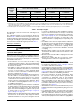
Pressure Switch Tubing
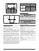
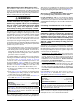
Figure 12 displays the proper routing of pressure switch
tubing for J962V*D furnaces. The J962V*D furnace
requires only one pair of switches to be connected to the
inducer’s static tap.
Accessories
The components in Figure 13 (page 16) & Figure 14 (page
16)
are included in the extra parts bag supplied with
the purchase of the J962V*D furnace. Depending on
your particular installation, some of these components
are optional and may not be used. Please refer to the
descriptions and accompanying figures when installing
these items.
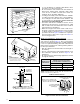
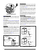
Finish Flange
The finish flange must be installed to vent the combustion
air pipe through the top of the furnace. NOTE: For proper
installation it is important that the pipe and screw holes in
the finish flange, gasket, and cabinet are aligned.
1. Position flange gasket over hole in the furnace cabinet.
2. Position finish flange on top of the flange gasket.
NOTE: Make sure the flange is properly oriented so
that the FRONT lettering is located near the front of
the furnace as shown in Figure 13.
3. Secure flange and gasket to cabinet with three field
supplied sheet metal screws.
Rubber Grommets
The 2 1/4” rubber grommet is used to seal the opening
between the furnace cabinet and the 2” PVC vent pipe.
The rubber grommet should be installed in the 3” hole
prior to running the vent pipe out of cabinet. No sealants
are required. See Figure 13.
The 7/8” rubber grommet is used to seal the opening
between the furnace cabinet and the gas pipe. The rubber
grommet should be installed in the 1 5/8” hole prior to
running the gas pipe into the cabinet. No sealants are
required.
The 3/4” rubber grommet is used if venting out the left
side of the cabinet and the drain tube is routed through
the blower deck. Remove the plastic plug from the hole
and install the grommet before routing the drain tube.
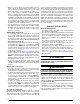
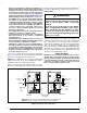
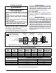
PVC Components
IMPORTANT NOTES:
• Before permanently installing these components,
it is recommended you dry-fit them first to ensure
proper fit and alignment with other vent pipes.
• The 2” PVC pipe shown in Figure 14 is not provided
in the extra parts bag.
• The PVC Tee & Trap are not included with the
J962V*D furnaces. However the PVC Trap (P/N
664659) can be purchased thru your local distributor.
The 2” PVC Tee and Trap are used when the inducer is
rotated to vent out thru the left or right side of the furnace
cabinet. See Figure 14.
Figure 12. Pressure Switch Tubing
for J962V*D Downflow Furnaces
AIRFLOW
123
4
567
8
FRONT
FRONT lettering must be
located near front
of furnace
Inlet Air
Finish
Flange
Flange
Gaskets
ø 2 1/4” Rubber
Grommet
ø 7/8” Rubber
Grommet
Figure 13. Finish Flange & Rubber Grommets
2” PVC Te e
2” PVC Pipe from Inline
Drain Assembly
(Not Included)
1/2” Tubing
(Field Supplied)
PVC
Trap
INSTALLATION OF PVC COMPONENTS
(TYPICAL ORIENTATION)
1/2” x 3/4”
Hose Barb
1/2” x 3/4”
Hose Barb
2” PVC Elbow
(Field Supplied)
2” PVC Te e
2” PVC Pipe from Inline
Drain Assembly
(Not Included)
1/2” Tubing
(Field Supplied)
PVC
Trap
INSTALLATION OF PVC COMPONENTS
(ALTERNATE ORIENTATION)
Figure 14. PVC Components