
J962V Installation Manual

15
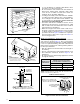
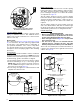
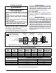
Installation on a concrete slab
1. Create an opening in the floor according to the
dimensions in Table 3.
2. Position the plenum and the furnace as shown in
Figure 11.
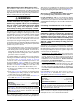
Inducer & Venting Options
To increase installation flexibility, the inducer assembly
can be rotated to 2 different positions (‘B’, ‘C’, & ‘D’
width cabinets only). Each variation has slightly different
requirements with regard to condensate disposal and, in
some cases, the need to seal the furnace cabinet.
Before using Table 4, the number of pipes (1-pipe or 2-pipe)
connected to the furnace must be known. First find the
side that the pipes will exit from the furnace and then
select the option that properly matches your installation
type from Figure 27 (page 33).
NOTE: It is important that Direct Vent (2-pipe) systems
maintain an airtight flow path from the air inlet to the flue
gas outlet. The furnace ships from the factory with two
holes in the cabinet for the air inlet and flue gas outlet.
In certain configurations, it is necessary to remove and
relocate a plastic cap in the furnace cabinet. If changing
the position of the air inlet and flue gas outlet, it is required
that the previous hole be closed off with the plastic cap to
maintain air tightness in the furnace. The hole locations
for J962V*D furnaces are shown in Figure 23 (page 26).
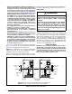
Inducer Assembly Rotation
WARNING:
Inducer rotation must be completed before
the furnace is connected to gas and electric. If
both utilities have been connected, follow the
shutdown procedures printed on the furnace
label and disconnect the electrical supply.
CAUTION:
It is good practice to label all wires prior to
disconnection. Wiring errors can cause improper
and dangerous operation.
1. Disconnect the electrical harness from the inducer
assembly.
2. Remove the inducer assembly ground wire from the
blower deck or door.
3. Remove 3 screws securing the inducer assembly to
the header box.
4. Remove drain tube from inline drain assembly.
5. Rotate the inducer assembly to its new position.
6. Secure the inducer assembly to the header box by
reinstalling the four screws. NOTE: An extra screw is
provided in the parts package with downflow furnaces.
7. Remove the cabinet plug from side of furnace and
reinstall in hole on opposite side of cabinet.
8. Connect all condensate drains as required for your
installation. See Table 4 (page 15), Figure 27 (page
33)
.
9. Reconnect the electrical harness to the inducer
assembly.
10. Reconnect the inducer assembly ground wire to the
blower deck or door.
11. Verify proper operation as detailed on the furnace
label.
Figure 11. Furnace on a Concrete Slab
Concrete
Floor
Furnace
Sheet
Metal
Plenum
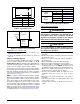
Table 4. Vent & Inducer Blower Options
B, C, & D, WIDTH CABINETS
VENT OPTIONS
1-Pipe
Options
Right
Option 1
Up
Option 2
Left
Option 3
2-pipe
Options
Right
Option 4
Up
Option 5
Left
Option 6
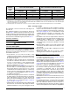
CABINET SIZE DIM. “A” DIM. “B”
B 16 5/8 19 1/4
C 20 1/8 19 1/4
D 23 5/8 19 1/4
NOTE: Dimensions shown in Inches.
“A”
“B”
Opening in concrete floor
Table 3. Cutout Dimensions