
J962V Installation Manual

14
produce a quieter installation, particularly in the heated
space. However, they can increase the pressure drop in
the duct system. Care must be taken to maintain the proper
maximum pressure rise across the furnace, temperature
rise and flow rate. This may mean increasing the duct
size and/or reducing the blower speed. These treatments
must be constructed and installed in accordance with
NFPA and SMACNA construction standards. Consult
with local codes for special requirements. For best sound
performance, be sure to install all the needed gaskets and
grommets around penetrations into the furnace, such as
for electrical wiring.
FURNACE INSTALLATION
General Requirements
• The J962V*D series gas furnace may only be installed
as a downflow application.
• The furnace must be leveled at installation and attached
to a properly installed duct system. See Figure 1 (page
6) for the required clearances needed to move the
furnace to its installation point (hallways, doorways,
stairs, etc).
• The furnace must be installed so that all electrical
components are protected from water.
• The furnace must be installed upstream from a
refrigeration system. (If applicable)
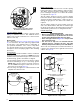
• The cabinet plug must always be used to close the hole
in the side of the furnace when rotating the inducer.
• The furnace requires special venting materials and
installation procedures. See page 7, page 8,
page 9, & page 10 for venting guidelines and
specifications.
WARNING:
The furnace must not be installed directly on
carpeting, tile, or any combustible material other
than wood flooring.
WARNING:
Failure to install the downflow sub-base kit may
result in fire, property damage or personal injury.
To install the furnace on combustible flooring, a special
sub-base is required. Downflow sub-base kits are factory
supplied accessories and are listed according to the
cabinet letter of the furnace. For ‘B’, ‘C’, and ‘D’ size
cabinets use Kit #904911. Please follow the instructions
provided with the kit.
A downflow sub-base kit is not necessary if the furnace
is installed on a factory or site-built cased air conditioning
coil. However, the plenum attached to the coil casing
must be installed so that its surfaces are at least 1” from
combustible construction.
• When a cooling system is installed which uses the
furnace blower to provide airflow over the indoor coil,
the coil must be installed downstream (on the outlet
side) of the furnace or in parallel with the furnace.
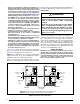
• If a cooling system is installed in parallel with the
furnace, a damper must be installed to prevent chilled
air from entering the furnace and condensing on the heat
exchanger. If a manually operated damper is installed,
it must be designed so that operation of the furnace is
prevented when the damper is in the cooling position
and operation of the cooling system is prevented when
the damper is in the heating position.
• It is good practice to seal all connections and joints
with industrial grade sealing tape or liquid sealant.
Requirements for sealing ductwork vary from region
to region. Consult with local codes for requirements
specific to your area.
Return Air Connections
• In applications where the supply ducts carry heated
air to areas outside the space where the furnace is
installed, the return air must be delivered to the furnace
by duct(s) secured to the furnace casing, running full
size and without interruption. Do not use the back of
the furnace for return air.
• Position the furnace with the return air ductwork ensuring
even alignment of furnace (or coil casing) air opening
and return air duct. NOTE: The ductwork must have an
opening equal to that of the return air opening of the
furnace (or coil casing). See Figure 23 (page 26) for
return air opening size.
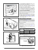
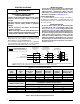
• To attach the return air duct to the downflow furnace,
bend the flanges on the furnace upward 90° with wide
duct pliers. See Figure 23 for furnace flange locations.
NOTE: If system installation includes AC coil casing,
bend the flanges on the coil casing upward 90° before
attaching the return air duct.
• Secure the return air ductwork to the furnace or coil
casing (if installed) with sheet metal screws. Make
sure the screws penetrate the sheet metal casing and
flanges.
Supply Air Connections
• The supply air must be delivered to the heated space
by duct(s) secured to the furnace or coil box casing,
running full size and without interruption.
• To attach the supply air duct, bend the flanges on the
furnace upward 90° with wide duct pliers. See Figure
23 (page 26)
for furnace flange locations. NOTE: If
system installation includes AC coil casing, bend the
flanges on the coil casing upward 90° before attaching
the supply air duct.
• Position the supply air ductwork onto the furnace
ensuring even alignment of furnace air opening and
supply air duct. NOTE: The ductwork must have an
opening equal to that of the supply air opening of the
furnace. See Figure 23 for supply air opening size.
Acoustical Treatments
Damping ducts, flexible vibration isolators, or pleated
media-style filters on the return air inlet of the furnace
may be used to reduce the transmission of equipment
noise eminating from the furnace. These treatments can