
J962V Installation Manual

11
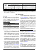
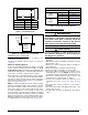
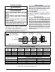
the equivalent of 2.5 feet of linear run. A 90 degree tee
is worth 7 ft.
The equivalent lengths of tees and various elbows are
listed in Table 1 . Measure the linear length of the vent run
and then add in the equivalent length of each fitting. The
total length, including the equivalent fitting lengths, must
be less than the maximum length specified in Table 1.
Vent Pipe Installation
CAUTION:
Combustion air must not be drawn from a
corrosive atmosphere.
This furnace has been certified for installation with zero
clearance between vent piping and combustible surfaces.
However, it is good practice to allow space for convenience
in installation and service.
• In the absence of local codes, the location of any
combustion air inlet relative to any vent terminal must
be at least 8 inches. This includes installations involving
more than one furnace.
• The quality of outdoor air must also be considered. Be
sure that the combustion air intake is not located near
a source of solvent fumes or other chemicals which
can cause corrosion of the furnace combustion system.
(See list of substances on page 5).
• Route piping as direct as possible between the furnace
and the outdoors. Horizontal piping from inducer to
the flue pipe must be sloped 1/4” per foot to ensure
condensate flows towards the drain tee or PVC trap.
Longer vent runs require larger pipe diameters. Refer
to the Inducer & Venting Options section on page 15
for additional information.
• If a Direct Vent (2-pipe) system is used, the combustion
air intake and the vent exhaust must be located in the
same atmospheric pressure zone. This means both
pipes must exit the building through the same portion
of exterior wall or roof as shown in Figure 7, Figure 8,
Figure 9
, & Figure 10 (page 12).
• Piping must be mechanically supported so that its weight
does not bear on the furnace. Pipe supports must be
installed a minimum of every 5 feet along the vent run
to ensure no displacement after installation. Supports
may be at shorter intervals if necessary to ensure that
there are no sagging sections that can trap condensate.
See Figure 28 (page 34). It is recommended to install
couplings along the vent pipe, on either side of the
exterior wall. These couplings may be required by local
code.
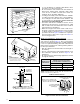
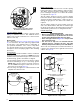
• If breakable connections are required in the combustion
air inlet pipe (if present) and exhaust vent piping, then
straight neoprene couplings for 2” or 3” piping with
hose clamps can be used. These couplings can be
ordered through your local furnace distributor. To install
a coupling:
1. Slide the rubber coupling over the end of the pipe that
is attached to the furnace and secure it with one of the
hose clamps.
2. Slide the other end of the rubber coupling onto the other
pipe from the vent.
3. Secure the coupling with the second hose clamp,
ensuring that the connection is tight and leak free.
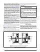
Outdoor Terminations - Horizontal Venting
• Vent and combustion air intake terminations shall
be installed as depicted in Figure 7 & Figure 8 and in
accordance with these instructions:
• Vent termination clearances must be consistent with the
NFGC, ANSI 2223.1/NFPA 54 and/or the CSA B149.1,
Natural Gas and Propane Installation Code. Table 12
(page 32)
lists the necessary distances from the vent
termination to windows and building air intakes.
• Vent and combustion air intake terminations must
be located to ensure proper furnace operation and
conformance to applicable codes. A vent terminal
must be located at least 3 feet above any forced air
inlet located within 10 feet. This does not apply to the
combustion air inlet of a direct vent (two pipe) appliance.
In Canada, CSA B149.1, takes precedence over these
instructions. See Table 12.
• All minimum clearances must be maintained to protect
building materials from degradation by flue gases. See
Figure 7.
• For optimal performance, vent the furnace through a
wall that experiences the least exposure to winter winds.
• The vent termination shall be located at least 3 ft.
horizontally from any electric meter, gas meter, regulator
and any relief equipment. These distances apply ONLY
Table 1. Vent Pipe Lengths
FURNACE
MODELS
(BTU)
SINGLE VENT PIPE LENGTH (FT.)
WITH 1 LONG RADIUS ELBOW*
DUAL VENT PIPE LENGTH (FT.)
WITH 1 LONG RADIUS ELBOW ON EACH PIPE*
OUTLET
2” DIAMETER
OUTLET
3” DIAMETER
INLET / OUTLET
2” DIAMETER
INLET / OUTLET
3” DIAMETER
60,000 60 90 60 90
80,000 30 90 30 90
100,000 30 90 25 90
115,000 N/A 90 N/A 90
*NOTES:
1. Subtract 2.5 ft. for each additional 2 inch long radius elbow, 5 ft. for each additional 2 inch short radius elbow, 3.5 ft. for each additional 3 inch
long radius elbow, and 7 ft. for each additional 3 inch short radius elbow. Subtract 5 ft for each 2” tee and 8 ft for each 3” tee. Two 45 degree
elbows are equivalent to one 90 degree elbow.
2. This table applies for elevations from sea level to 2,000 ft. For higher elevations, decrease pipe lengths by 8% per 1,000 ft of altitude.