
J962V Installation Manual

10
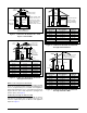
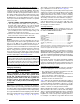
Alternate Method of Providing Air from Outside:
If acceptable under local Codes, it is permitted to provide
outside air using one opening (See NFGC). Generally,
confined spaces must have 2 openings in the space for
combustion air. One opening must be within 12 inches of
the ceiling, and the other must be within 12 inches of the
floor. However, an alternative method recently adopted by
the NFGC uses one opening within 12 inches of the top
of the space. This method may be used if it is acceptable
to the local codes.
THE FOLLOWING CONDITIONS MUST BE MET:
1. The opening must start within 12” of the top of the
structure and connect with the out of doors through
vertical or horizontal ducts or be ducted to a crawl or
attic space that connects with the out of doors.
2. The opening must have a minimum free area of 1 in
2
.
per 3,000 Btu per hour of the total input rating of all
equipment located in the enclosure.
3. The free area must not be less than the sum of all the
areas of the vent connectors in the enclosure.
Conventional Vent Systems - Unconfined
Spaces
An unconfined space is an area including all rooms not
separated by doors with a volume greater than 50 cubic
feet per 1,000 Btuh of the combined input rates of all
appliances which draw combustion air from that space.
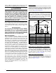
In general, a furnace installed in an unconfined space will
not require outside air for combustion. However, in homes
built for energy efficiency (low air change rates), it may
be necessary to provide outside air to ensure adequate
combustion and venting, even though the furnace is located
in an unconfined space. See Example below.
EXAMPLE
A space with a water heater rated at 45,000 Btuh input
and a furnace rated at 75,000 Btuh requires a volume of
6,000 cubic feet [50 x (45 + 75) = 6,000] to be considered
unconfined. If the space has an 8 foot ceiling, the floor
area of the space must be 750 sq. ft. (6,000 / 8 = 750).
Category IV Venting
WARNING:
Upon completion of the furnace installation,
carefully inspect the entire flue system both
inside and outside the furnace to assure it is
properly sealed. Leaks in the flue system can
result in serious personal injury or death due
to exposure of flue products, including carbon
monoxide.
This furnace is classified as a “Category IV” appliance,
which requires special venting materials and installation
procedures. This section specifies installation requirements
for Conventional (1-pipe) and Direct Vent (2-pipe) piping.
For 1- pipe installations, install vent piping as described in
this section and provide air for combustion and ventilation
according to page 7, page 8, page 9, & page 10.
The length of vent and combustion air piping for either
type of installation are shown in Table 1 (page 11).
Category IV appliances operate with positive vent pressure
and therefore require vent systems which are thoroughly
sealed. They also produce liquid condensate, which is
slightly acidic and can cause severe corrosion of ordinary
venting materials. Furnace operation can be adversely
affected by restrictive vent and combustion air piping.
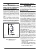
The inducer assembly on this furnace can be rotated to
vent the flue products out of the left or right side of the
furnace. This increases the flexibility of which direction
the vent pipe can exit the furnace.
Vent Pipe Material
Vent and combustion air pipe and fittings must be one
of the following materials in the list and must conform to
the indicated ANSI/ASTM standards.
MATERIALS STANDARDS
Schedule 40PVC ................................................................ D1785
PVC-DWV ........................................................................... D2665
SDR-21 & SDR-26 .............................................................. D2241
ABS-DWV ........................................................................... D2661
Schedule 40 ABS ............................................................... F628
Foam / Cellular Core PVC .................................................. F891
*PolyPro
®
by DuraVent ....................................................... ULC-S636
CPVC .................................................................................. D1784
*When using PolyPro
®
, all venting and fittings must be from the same
manufacturer with no interchanging of other materials. Refer to specific
instructions supplied with the PolyPro vent kits
When joining PVC to PVC, use cement that conforms to
ASTM standard D2564. PVC primer must meet standard
ASTM F656. When joining ABS to ABS, use cement that
conforms to ASTM standard D2235. When joining PVC to
ABS, use cement as specified in procedure from ASTM
standard D3138
In Canada, all plastic vent pipes and fittings including
any cement, cleaners, or primers must be certified as a
system to ULC S636. However this requirement does not
apply to the finish flanges or piping internal to the furnace.
Vent Pipe Length & Diameter
In order for the furnace to operate properly, the combustion
air and vent piping must not be excessively restrictive.
• The venting system should be designed to have the
minimum number of elbows or turns.
• Transition to the final vent diameter should be done as
close to the furnace outlet as practical.
• Always use the same size or a larger pipe for combustion
air that is used for the exhaust vent.
Table 1 indicates the maximum allowable pipe length for
a furnace of known input rate, when installed with piping
of selected diameter and number of elbows. To use the
table, the furnace input rate, the centerline length and the
number of elbows on each pipe must be known.
When estimating the length of vent runs, consideration
must be made to the effect of elbows and other fittings.
This is conveniently handled using the idea of “equivalent
length”. This means the fittings are assigned a linear
length that accounts for the pressure drop they will cause.
For example: a 2” diameter, long radius elbow is worth