
J962V Installation Manual

34
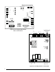
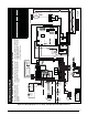
Figure 29. J962V*D Component Locations
AIR FLOW
1 2 3
4
5 6 7
8
Burner
Assembly
Flame Sensor
Roll-Out
Switch
Finish Flange
Blower Assembly
(behind
blower panel)
Blower Door Switch
(behind blower panel)
Motor Choke
(C & D cabinets only)
Gas
Manifold
Gas Valve
Igniter
Inducer Assembly
Vent Limit Switch
Main Air Limit Switch
Fur
nace Control Board
Motor Control Board
Pressure Switches
Transformer
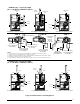
Figure 28. Horizontal & Vertical Venting
(B, C, & D Width Cabinets)
HORIZONTAL VENTING W/ 2-PIPES
(B, C, & D WIDTH CABINETS)
Couplings with
2 Hose Clamps
(Optional)
VERTICAL VENTING W/ 2-PIPES
(B, C, & D WIDTH CABINETS)
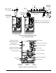
FLUE PIPE
NOTE: Straps or other suitable supports at
minimum of 5 ft. Intervals. First support placed
as close to furnace connection as possible.
Upward Pitch - 1/4” per foot
(Flue Pipe)
COMBUSTION
AIR
90°
Elbow
Support System
on Vertical Rise
COMBUSTION AIR
Wall
Normal
Snow Level
Seal/Caulk
Around Pipes
at Building
90°
Elbow
7”
12”
Min.
AIR FLOW
1 2 3
4
56 7
8
AIR FLOW
1 2 3
4
56 7
8
FLUE PIPE
Couplings with
2 Hose Clamps
(Optional)
See Note