
J952V Installation Manual

24
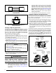
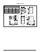
c. Using an Allen wrench, turn the the LO Input
Adjusting Screw on the LO side of the regulator to
adjust the reduced input setting or turn the HI Input
Adjusting Screw on the side of the regulator to adjust
the full input setting. See
Figure 25 (page 24).
NOTE: Turning the adjusting screw clockwise
increases the pressure and counterclockwise
reduces the pressure.
d. Reinstall plastic cap after adjustment is complete.
Verifying & Adjusting Temperature Rise
Confirm the temperature rise through the furnace is within the
limits specified on the furnace rating plate. Any temperature
rise outside the specified limits could result in premature
failure of the heat exchanger.
1. Place thermometers in the return and supply air stream as
close to the furnace as possible. To avoid false readings,
the thermometer on the supply air side must be shielded
from direct radiation from the heat exchanger.
2. Adjust all registers and duct dampers to the desired
position and run the furnace for 10 to 15 minutes in high fire
before taking any temperature readings. The temperature
rise is the difference between the supply and return air
temperatures.
For typical duct systems, the temperature rise will fall within the
limits specified on the rating plate with the blower speed at the
factory recommended setting. If the measured temperature
rise is outside the specified limits, it may be necessary to
change the speed of the blower. NOTE: Lowering the blower
speed increases the temperature rise and a higher blower
speed will decrease the temperature rise.
Verifying & Adjusting Input Rate
The input rate must be verified for each installation to prevent
over-firing of the furnace. NOTE: The input rate must not
exceed the rate shown on the furnace rating plate. At altitudes
above 2,000 feet, it must not exceed that on the rating plate
less 4% for each 1,000 feet. To determine the exact input
rate, perform the following procedures:
1. Shut off all other gas fired appliances.
2. Start and run the furnace in high fire for at least 3 minutes.
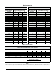
3. Measure the time (in seconds) required for the gas meter
to complete one revolution.
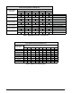
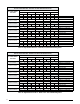
4. Convert the time per revolution to cubic feet of gas per
hour using
Table 5 (page 28).
5. Multiply the gas flow rate in cubic feet per hr by the heating
value of the gas in Btu per cubic ft to obtain the input rate
in Btuh. See example below.
EXAMPLE:
• Time for 1 revolution of a gas meter with a 1 cubic ft
dial = 40 seconds.
• From
Table 5 read 90 cubic ft gas per hr.
• Local heating value of the gas (obtained from gas
supplier) = 1,040 Btu per cubic ft.
• Input rate = 1,040 x 90 = 93,600 Btuh.
6. The manifold pressure must be set to the appropriate
value for each installation by a qualified installer, service
agency or the gas supplier.
WARNING:
Do not attempt to drill the gas orifices. Use only
factory supplied orifices. Improperly drilled
orifices may cause fire, explosion, carbon
monoxide poisoning, personal injury or death.
a. Remove plastic cap from pressure regulator.
b. Obtain the manifold pressure setting required for
this installation by referring to
Table 7 (page 29)
for Propane or
Table 9 & Table 10 (page 30) for
Natural Gas.
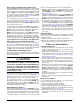
Figure 24. DEHUM Wiring Configuration
without Humidistat
DEHUM
R
BLOWER CONTROL
C
O (B)
ADDED RELAY
(Normally Open)
Figure 25. HI & LO Input Adjusting Screws
IN
ON
OFF
Inlet
Pressure
Ta p
Inlet
Pressure
Ta p
Manifold
Pressure
Ta p
Manifold
Pressure
Ta p
2-STAGE GAS VALVES
Model VR8205Q2381
Model VR9205Q1028
ON / OFF
Knob
ON / OFF
Switch
HI Input
Adjusting
Screw
Lo Input
Adjusting
Screw
HI Input
Adjusting
Screw
Lo Input
Adjusting
Screw
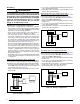
DHUM
R
R
DHUM
HUMIDISTAT
MOTOR
CONTROL BO
ARD
Figure 23. DEHUM Wiring Configuration
with Humidistat