
J952V Installation Manual

23
Autostaging for Single Stage Thermostats
The Autostaging feature makes it possible to use a single stage
thermostat and still receive some of the benefits of 2-stage
furnace operation. If Autostage is enabled, the furnace will
drop to LOW fire after initially starting in HIGH fire. After a
period of 10 minutes, the furnace will then stage up to HIGH
fire, until the heating load is met. See
Figure 20 and the Low
Voltage Connection section on
page 22.
The autostaging option on the furnace control board is
selected using the autostage jumper located near the
thermostat terminal block. See
Figure 28 (page 31). When
the autostage jumper is moved from OFF to ON, the following
occurs during a call for heat:
Setting the Autostage jumper in the ON position signals the
control to utilize a 10 minute delay between LOW fire and
HIGH fire when a call for heat is supplied via 24V signal to
W1. This setting is the same as jumping R to W2.
NOTE: If the autostage jumper is in the ON position and a
W1 demand is present when power is applied to the furnace,
the first heat cycle will run in second stage heat with no
autostaging. After the first cycle, the furnace will resume
normal autostaging operation. DO NOT jump W1 & W2
together while the autostage jumper is in the ON position.
Autostaging for Two-Stage Thermostats
The Autostage setting on the furnace control board Figure
28 (page 31)
is disabled when shipped from the factory.
This feature will be not used when paired with a two-stage
thermostat. The autostage jumper setting (P7) must be kept
on OFF to allow the thermostat to adjust stages.
Variable Speed Blower Application
The J952V*U furnace uses a high efficiency circulating air
motor and a variable speed motor control board to maintain
constant CFM airflow.
CAUTION:
The variable speed control board is used by
other appliances. Many of the terminals and
connections on the board are for other appliances
and are not used in the two stage application.
The only two-stage field connection to this board
is the DHUM terminal, used to reduce the blower
speed during cooling.
The variable speed motor control board shown in Figure 27
(page 31)
has a set of dip switches for setting the base
blower speed. Use pins 1 to 4 to set the blower speed for
heating and pins 5 to 8 to set the speed for cooling.
Use field supplied wire to connect the thermostat’s
dehumidifier output to the terminal marked DEHUM. The
thermostat should be set so that the DEHUM output is
high (positive) when dehumidification is needed. See also
Dehumidification Options section.
Dehumidification Options
The motor control board (Figure 27) has a DEHUM connection
that allows the system to increase the amount of humidity that
is removed from the circulating air. This is accomplished by
reducing the CFM and allowing the cooling coil to become
colder. This will only occur when there is a call for cooling.
There are many ways that this can be electrically wired:
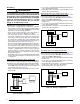
• If the room thermostat incorporates a humidity sensor and
DEHUM output, connect the DEHUM on the thermostat
to the DEHUM terminal on the motor control board. See
Figure 23 (page 24).
• If using a separate humidistat, connect the DEHUM & R
terminals on the humidistat to the DEHUM & R terminals on
the motor control board. See
Figure 27. In this option, the
DEHUM output of the humidistat must be set to be normally
open and closed when there is a call for humidification.
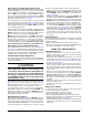
• If a humidistat is not available, it is an acceptable option
to connect the R & DEHUM via a field supplied normally
open relay. See
Figure 24 (page 24). The R & DEHUM
terminals should be connected across the normally open
relay terminals. The O (B) & C terminals should then be
connected across the relay coil. This option causes the
blower to run at a reduced CFM for 10 minutes after a call
for cooling.
Heat Anticipator
Set the heat anticipator according to the instructions supplied
by the thermostat manufacturer. To determine the heat
anticipator setting:
1. Add the current draw of the system components; or
2. Measure the current flow on the thermostat R & W circuit
after the circulating blower motor has started.
START-UP & ADJUSTMENTS
Pre-Start Check List
√ Verify the polarity of the connections are correct, the line
voltage power leads are securely connected and the
furnace is properly grounded.
√ Verify that all needed thermostat wires are securely
connected to the correct leads on the terminal strip of the
circuit board. See
Figure 20 (page 22), Figure 21 (page
22)
, & Figure 22 (page 22).
√ Verify the gas line service pressure does not exceed 10.0
inches of water column, and is not less than 4.5 inches
W.C. for natural gas. For LP gas the line service pressure
must not exceed 14 in. W.C., and must not be less than
11.0 in. W.C.
√ Verify the roll-out and manual reset switch is closed. If
necessary, press the button to reset the switch. DO NOT
install a jumper wire across a switch to defeat its
function. If a switch reopens on start-up, DO NOT reset
the switch without identifying and correcting the fault
condition.
√ Verify the blower door is in place, closing the door switch
in the line voltage circuit.
√ Verify the gas line has been purged and all connections
are leak free.
Start-up Procedures
Do not perform these steps until all of the checks in the
previous steps have been completed:
1. Set the thermostat to the lowest setting.
2. Turn off all electrical power to the furnace.
3. Follow the Operating Instructions on the furnace label.
4. Set the thermostat above room temperature and verify
the Operating Sequence. See
page 25.
5. After 5 minutes of operation, set the thermostat below room
temperature and verify steps 11 & 12 of the Operating
Sequence.