
J952V Installation Manual

22
Grounding
WARNING:
To minimize personal injury, the furnace cabinet
must have an uninterrupted or unbroken electrical
ground. The controls used in this furnace require
an earth ground to operate properly. Acceptable
methods include electrical wire or conduit
approved for ground service. Do not use gas
piping as an electrical ground!
Thermostat / Low Voltage Connections
• The furnace is designed to be controlled by a 24 VAC
thermostat. The thermostat’s wiring must comply with the
current provisions of the NEC (ANSI/NFPA 70) and with
applicable local codes having jurisdiction.
• Trane doesn’t support twinning of two stage furnaces.
Please contact your furnace distributor for details.
• The thermostat must be installed according to the
instructions supplied by the thermostat manufacturer.
Low voltage connections (24 VAC) from the thermostat
are wired to the terminal strip on the integrated control
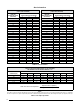
in the furnace. Recommended minimum wire gauge for
thermostat wiring is shown in
Table 4 (page 21).
• The thermostat should be mounted about 5 feet above the
floor on an inside wall. DO NOT install the thermostat on
an outside wall or any other location where its operation
may be adversely affected by radiant heat from fireplaces,
sunlight, or lighting fixtures, and convective heat from
warm air registers or electrical appliances. Refer to the
thermostat manufacturer’s instruction sheet for detailed
mounting information.
• Depending on the type of air conditioning unit and thermostat
used, both blower applications utilize three basic wiring
configurations.
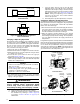
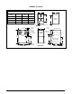
Single Stage AC & Single Stage Thermostat
This option does not use the full two-stage control capability
of the furnace, but the possibility of timed autostaging is
available. See also Autostaging for Single Stage Thermostats.
• Connect the thermostat’s W output to the furnace control
boards W1 terminal. This allows the furnace to always run
in low output mode. See
Figure 20.
• Always connect the thermostat C & R to the furnace control
board C & R.
• For cooling, connect the thermostats Y signal to the furnace
control board Y / Y2 terminal.
• Field supplied wires should also connect Y / Y2 & C to the
outdoor unit’s Y & C terminals.
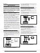
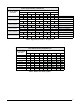
Single Stage AC & Two Stage Thermostat
This option uses the full two stage heating capability of the
furnace with a single stage outdoor unit. See
Figure 21.
• Connect the thermostat’s W1 & W2 outputs to the furnace
control board’s W1 & W2 terminals.
• Always connect the thermostat C & R to the furnace control
board C & R
• For cooling, connect the thermostats Y signal to the furnace
control board Y / Y2 terminal.
• Field supplied wires should also connect Y / Y2 & C to the
outdoor unit’s Y & C terminals.
Figure 21. Wiring Configuration 2
DHUM
A/C CONDENSING UNIT
(SINGLE STAGE)
HIGH EFFICIENCY
BLOWER MOTOR
CONTROL BO
ARD
C
Y
R DHUMC
Y
G
ROOM THERMOSTAT
(TWO - STAGE)
W
1
W
2
TWO STAGE FURNACE BOARD
R
C
Y/Y2
W2
G
W1
Y1
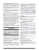
A/C CONDENSING UNIT
(TWO STAGE)
HIGH EFFICIENCY
BLOWER MOTOR
CONTROL BO
ARD
DHUM
C
Y2
Y1
R DHUMC
Y
2
G
ROOM THERMOSTAT
(TWO STAGE)
W
1
W
2
TWO STAGE FURNACE BOARD
Y
1
R
C
Y/Y2
W2
G
W1
Y1
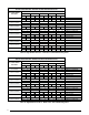
Figure 22. Wiring Configuration 3
Figure 20. Wiring Configuration 1
R DHUM
C
Y
G
W
1
ROOM THERMOSTAT
(SINGLE STAGE)
DHUM
A/C CONDENSING UNIT
(SINGLE STAGE)
C
R
C
Y/Y2
Y
W2
G
W1
Y1
HIGH EFFICIENC
Y
BLOWER MOTOR
CONTROL BOAR
D
TWO STAGE FURNACE BOARD
Two-Stage AC & Two-Stage Thermostat
This option uses the full two stage heating capability of the
furnace with a two stage outdoor unit. See
Figure 22.
• Connect the thermostat’s W1 & W2 outputs to the furnace
control board’s W1 & W2 terminals.
• Always connect the thermostat C & R to the furnace control
board C & R.
• For cooling, connect the thermostat Y & Y1 to the furnace
control board’s Y / Y2 & Y1 terminal’s.
• Field supplied wires should also connect the Y / Y2 & Y1
signals to the outdoor unit’s Y & Y1 terminals.
• Connect terminal C to the outdoor unit’s C.