
J952V Installation Manual

17
3. Install the 1/2” x 1/2” hose barb on the 2” PVC reducer.
NOTE: Do not over tighten! Use an adequate amount of
Teflon tape on the threads. Do not use liquid sealants.
4. Verify all connections and joints for tight fit and proper
alignment with other vent pipes.
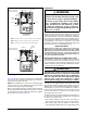
Alternate Orientation
1. Install the 2” PVC Tee horizontally on the 2” vent pipe that
is extending out the side of the cabinet. Permanently bond
them together using appropriate primer and cement. Refer
to the alternate orientation shown in
Figure 15.
2. Install the 2” PVC Elbow on the end of the 2” PVC Tee.
Permanently bond them together using appropriate primer
and cement.
3. Install the reducer or PVC trap (if supplied) on the bottom
end of the PVC Tee. Permanently bond them together
using appropriate primer and cement.
4. Install the 1/2” x 1/2” hose barb on the 2” PVC reducer.
NOTE: Do not over tighten! Use an adequate amount of
Teflon tape on the threads. Do not use liquid sealants.
5. Verify all connections and joints for tight fit and proper
alignment with other vent pipes.
Condensate Drain Lines
IMPORTANT NOTE
If the furnace is installed in an area where temperatures
fall below freezing, special precautions must be made
for insulating condensate drain lines that drain to the
outdoors. If condensate freezes in the lines, this will
cause improper operation or damage to the furnace. It
is recommended that all drain lines on the outside of
the residence be wrapped with an industry approved
insulation or material allowed by local code.
The placement of the condensate drain lines will depend on
the configuration selected in
Table 3 (page 15). The drain
lines can be routed out the left or right side of the furnace,
but must maintain a downward slope to ensure proper
condensate drainage.
The J-trap may need to be rotated to the side that matches
your setup in
Figure 32 (page 36), Figure 33 (page 37),
Figure 34 (page 38) & Figure 35 (page 39). To rotate the
J-trap, loosen the clamp on the drain tube, rotate the J-trap
to either side, and retighten the clamp.
It is permissible to locate the trap away from the furnace. The
condensate drain system (J-trap and drain tube) should be
no more than 30 equivalent feet while maintaining 1/4” per
foot slope, and insulated if located in an unconditioned space.
THREE GENERAL RULES APPLY:
• Each condensate drain line must be separately trapped
using a J-Trap or field supplied loop. After individually
trapping the condensate lines, it is acceptable to combine
the drains.
• There must always be a drain attached to the collector at
the outlet of the secondary heat exchanger.
• There must always be a drain at the lowest point of the
venting system. NOTE: If using a condensate pump, the
furnace drain line must be installed above the pumps water
line.
EXCEPTIONS AND CLARIFICATIONS TO THE
GENERAL RULES:
• In some cases, the lowest point in the vent system is where
it connects to the inducer (
Option 12 & Option 14). In this
case one drain at this location is sufficient.
• If the vent exits the furnace horizontally, the vent may be
turned vertically with a tee. The drip leg formed by the
tee must include a drain (
Option 3, Option 4, Option 5, &
Option 6).
• In certain cases, it is permitted to drain the inducer back
into the top drain of the collector (
Option 3, Option 5, Option
11
, & Option 13). To ensure proper drainage of condensate,
make sure the drain line does not sag or becomes twisted.
The drain tube supplied with the furnace may need to be
trimmed.
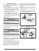
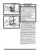
Bottom Panel Removal
The steps listed below describe how to remove the bottom
panel from the furnace. See
Figure 16 (page 18).
1. Remove the door from the blower compartment.
2. Disconnect the blower motor wiring harness from the
control board.
3. Remove two screws securing the blower assembly to the
furnace.
4. Carefully pull the blower assembly out thru the front of the
furnace.
5. Remove all screws securing bottom panel to bottom of
furnace and front brace.
6. Lift up and slide bottom panel out through front of furnace.
7. Reinstall the blower assembly in reverse order.
Alternate Bottom Panel Removal
If the bottom panel cannot be removed using the previous
instructions, the steps below are an alternate method for
removing the bottom panel. See
Figure 17 (page 18).
1. Remove the door from the blower compartment
2. Remove all screws securing the bottom panel to the front
brace.
3. Remove two screws securing the furnace cabinet to the
blower deck.
4. Remove all screws securing the furnace cabinet to the
bottom pane.
5. Remove the screw securing the bottom corner of the
furnace cabinet to the front brace.
6. Carefully spread the bottom corner of the furnace cabinet
outwards while sliding the bottom panel out through the
front of the furnace.
7. Reassemble the furnace in reverse order.