
J952V Installation Manual

14
FURNACE INSTALLATION
J952V*U series gas furnaces offer a wide range of installation
options, including installation in the upflow or horizontal
positions with either right, left, or upflow return air.
General Requirements
• The furnace must be leveled at installation and attached to
a properly installed duct system. See
Figure 1 (page 5)
for the required clearances needed to move the furnace
to its installation point (hallways, doorways, stairs, etc).
• The furnace must be installed so that all electrical
components are protected from water.
• The furnace must be installed upstream from a refrigeration
system. (If applicable)
• The cabinet plug must always be used to close the hole
in the side of the furnace when rotating the inducer.
• The furnace requires special venting materials and
installation procedures. Refer to the Combustion Air &
Venting Requirements section (
page 6) for venting
guidelines and specifications.
Upflow Furnaces
WARNING:
The furnace must not be installed directly on
carpeting, tile, or any combustible material other
than wood flooring.
J952V*U series gas furnaces are shipped with the bottom
panel installed as shown in
Figure 16 (page 18). If the
furnace is installed with only side return air, the bottom panel
must not be removed. If the furnace is installed with bottom
return air, the bottom panel must be removed. See Bottom
Panel Removal on
page 17.
Horizontal Furnaces
WARNING:
The furnace must not be installed directly on
carpeting, tile, or any combustible material other
than wood flooring.
The J952V*U series gas furnace can be installed horizontally
(
Figure 11) in an attic, basement, crawl space or alcove. It
can also be suspended from a ceiling in a basement or utility
room in either a right to left airflow or left to right airflow as
shown in
Figure 12.
J952V*U series furnaces are shipped with the bottom panel
installed. If furnace is installed horizontally, remove the bottom
panel from the furnace before attaching the duct system. See
Bottom Panel Removal section (
page 17).
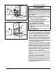
If installing the furnace with an evaporator coil (in an
attic), it is required that a drip pan be placed under the
furnace. If the installation is on a combustible platform
(
Figure 11), it is recommended that the drip pan extend
at least 12 inches past the top and front of the furnace.
NOTE: Although it is not required to use a drip pan for heat
only applications, state and local codes may require it.
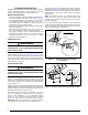
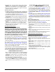
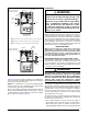
If the furnace will be suspended from the ceiling, assemble a
support frame (
Figure 12) using slotted iron channel and full
threaded rod. Fasten the frame together with nuts, washers,
and lockwashers. Secure the support frame to the rafters
with lag bolts.
NOTE: The furnace can also be suspended using steel
straps around each end of the furnace. The straps should
be attached to the furnace with sheet metal screws and to
the rafters with bolts.
It is recommended for further reduction of fire hazard that
cement board or sheet metal be placed between the furnace
and the combustible floor and extend 12 inches beyond the
front of the door and top of the furnace.
Figure 12. J952V*U Horizontally Suspended in Attic
Lag
Bolt
Nuts (x2)
Washer
and
Lockwasher
Nuts (x2)
Threaded
Rod
Flue pipe vented
to outside
J-Trap
Height
3” Min.
Coil Plenum
Wood or
non-combustible
platform
Two-pipe installation shown
Combustion Air
Condensate
Drain Lines
Figure 11. J952V*U Horizontally Installed
on a Platform