
J952V Installation Manual

13
damper is in the cooling position and operation of the
cooling system is prevented when the damper is in the
heating position.
• It is good practice to seal all connections and joints with
industrial grade sealing tape or liquid sealant. Requirements
for sealing ductwork vary from region to region. Consult
with local codes for requirements specific to your area.
Return Air Connections
• In applications where the supply ducts carry heated air to
areas outside the space where the furnace is installed,
the return air must be delivered to the furnace by duct(s)
secured to the furnace casing, running full size and without
interruption. Do not use the back of the furnace for
return air.
• Position the furnace with the return air ductwork ensuring
even alignment of furnace (or coil casing) air opening and
return air duct. NOTE: The ductwork must have an opening
equal to that of the return air opening of the furnace (or coil
casing). See
Figure 26 (page 27) for return air opening
size.
Upflow & Horizontal Furnaces
• The return air ductwork may be connected to the left side,
right side, or bottom of the furnace. NOTE: If using the left
or right side of the furnace for return air, the bottom panel
(
Figure 26) must not be removed from the bottom of the
furnace.
WARNING:
The bottom panel of the furnace must be in
place when the furnace is installed with side
return air ducts. Removal of all or part of the
base could cause circulation of combustible
products into the living space and create
potentially hazardous conditions, including
carbon monoxide poisoning that could result in
personal injury or death.
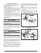
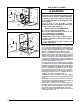
• Side Return Installations: To attach the return air duct
to the left or right side of the furnace, punch out the 4
knockouts from the side of the furnace (
Figure 26 (page
27)
). Using sharp metal cutters, cut an opening between
all 4 knockouts to expose the blower assembly. Position
the return air duct over the opening and secure to the side
with sheet metal screws.
• Bottom Return Installations: If using the bottom of the
furnace for return air, the bottom panel (
Figure 26) must be
removed from the bottom of the furnace. See
page 17 for
removal instructions. Position the furnace over the return
air duct and secure together with sheet metal screws. Make
sure the screws penetrate the duct and furnace casing.
Supply Air Connections
• The supply air must be delivered to the heated space by
duct(s) secured to the furnace or coil box casing, running
full size and without interruption.
• To attach the supply air duct to upflow & horizontal furnaces,
bend the flanges on the furnace upward 90° with wide
duct pliers. See
Figure 26 (page 27) for furnace flange
locations. NOTE: If system installation includes AC coil
casing, bend the flanges on the coil casing upward 90°
before attaching the supply air duct.
• Position the supply air ductwork onto the furnace ensuring
even alignment of furnace air opening and supply air duct.
NOTE: The ductwork must have an opening equal to that
of the supply air opening of the furnace. See
Figure 26 for
supply air opening size.
Acoustical Treatments
Damping ducts, flexible vibration isolators, or pleated media-
style filters on the return air inlet of the furnace may be used
to reduce the transmission of equipment noise eminating
from the furnace. These treatments can produce a quieter
installation, particularly in the heated space. However, they
can increase the pressure drop in the duct system. Care
must be taken to maintain the proper maximum pressure rise
across the furnace, temperature rise and flow rate. This may
mean increasing the duct size and/or reducing the blower
speed. These treatments must be constructed and installed in
accordance with NFPA and SMACNA construction standards.
Consult with local codes for special requirements. For best
sound performance, be sure to install all the needed gaskets
and grommets around penetrations into the furnace, such
as for electrical wiring