
J952V Installation Manual

12
18 inches of vent pipe can be reduced. It is acceptable
to reduce from 3” to 2-1/2”, 3” to 2”, or 2” to 1-1/2” if the
total vent length is at least 15 feet in length and the vent
length is within the parameters specified in
Table 1. The
restriction should be counted as 3 equivalent feet. Smaller
vent pipes are less susceptible to freezing, but must not
be excessively restrictive. The length of the 2 inch pipe
must not be longer than 18 inches.
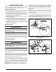
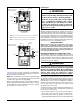
• If furnace is installed horizontally, make sure the drainage
port on the in-line drain assembly is pointed downward
to ensure proper drainage of condensate. See
Figure 34
(page 38)
& Figure 35 (page 39).
• To prevent debris or creatures from entering the combustion
system, a protective screen may be installed over the
combustion air intake opening. The screens hole size
must be large enough to prevent air restriction.
Existing Installations
When an existing furnace is removed from a vent system
serving other appliances, the existing vent system may not
be sized properly to vent the remaining appliances (For
example: water heater). An improperly sized venting system
can result in the formation of condensate, leakage, or spillage.
The existing vent system should be checked to make sure
it is in compliance with NFGC and must be brought into
compliance before installing the furnace.
NOTE: If replacing an existing furnace, it is possible you will
encounter an existing plastic venting system that is subject
to a Consumer Product Safety Commission recall. The pipes
involved in the recall are High Temperature Plastic Vent
(HTPV). If your venting system contains these pipes DO
NOT reuse this venting system! This recall does not apply
to other plastic vent pipes, such as white PVC or CPVC.
Check for details on the CPSC website or call their toll-free
number (800) 758-3688.
Condensate Disposal
The method for disposing of condensate varies according
to local codes. Consult your local code or authority having
jurisdiction.
Each of the condensate drain lines must be J-trapped using
field supplied parts. After the condensate lines are J-trapped,
they may be combined together into a single run to the drain.
The drain lines must be routed downward to ensure proper
drainage from furnace.
Neutralizer kit P/N 902377 is available for use with this furnace.
Please follow the instructions provided with the kit.
For Installations where there is limited clearance for the
J-Trap (such as an attic where it may be installed between
ceiling joists), either side of the J-Trap can be shortened to
a minimum of 3 Inches. See
Figure 11, (page 14).
CIRCULATING AIR REQUIREMENTS
WARNING:
Do not allow combustion products to enter the
circulating air supply. Failure to prevent the
circulation of combustion products into the
living space can create potentially hazardous
conditions including carbon monoxide poisoning
that could result in personal injury or death.
All return ductwork must be secured to the
furnace with sheet metal screws. For installations
in confined spaces, all return ductwork must be
adequately sealed. When return air is provided
through the bottom of the furnace, the joint
between the furnace and the return air plenum
must be air tight.
The surface that the furnace is mounted on must
provide sound physical support of the furnace
with no gaps, cracks or sagging between the
furnace and the floor or platform.
Return air and circulating air ductwork must
not be connected to any other heat producing
device such as a fireplace insert, stove, etc. This
may result in fire, explosion, carbon monoxide
poisoning, personal injury, or property damage.
Plenums & Air Ducts
• Plenums and air ducts must be installed in accordance with
the Standard for the Installation of Air Conditioning and
Ventilating Systems (NFPA No. 90A) or the Standard for
the Installation of Warm Air Heating and Air Conditioning
Systems (NFPA No. 90B).
• If the maximum airflow is 1,600 CFM or more, it is required
that two openings be used for return air on upflow furnaces.
• It is recommended that the outlet duct contain a removable
access panel. The opening should be accessible when the
furnace is installed in service and shall be of a size that
smoke or reflected light may be observed inside the casing
to indicate the presence of leaks in the heat exchanger.
The cover for the opening shall be attached in such a way
as to prevent leaks.
• If outside air is used as return air to the furnace for
ventilation or to improve indoor air quality, the system must
be designed so that the return air is not less than 60° F
(15° C) during operation. If a combination of indoor and
outdoor air is used, the ducts and damper system must
be designed so that the return air supply to the furnace is
equal to the return air supply under normal, indoor return
air applications.
• When a cooling system is installed which uses the furnace
blower to provide airflow over the indoor coil, the coil must
be installed downstream (on the outlet side) of the furnace
or in parallel with the furnace.
• If a cooling system is installed in parallel with the furnace, a
damper must be installed to prevent chilled air from entering
the furnace and condensing on the heat exchanger. If a
manually operated damper is installed, it must be designed
so that operation of the furnace is prevented when the