
J952V Installation Manual

11
ensure no displacement after installation. Supports may be
at shorter intervals if necessary to ensure that there are no
sagging sections that can trap condensate. See
Figure 30
(page 34)
and Figure 31 (page 35). It is recommended
to install couplings along the vent pipe, on either side of
the exterior wall. These couplings may be required by local
code.
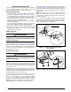
• If breakable connections are required in the combustion air
inlet pipe (if present) and exhaust vent piping, then straight
neoprene couplings for 2” or 3” piping with hose clamps
can be used. These couplings can be ordered through
your local furnace distributor. To install a coupling:
1. Slide the rubber coupling over the end of the pipe that is
attached to the furnace and secure it with one of the hose
clamps.
2. Slide the other end of the rubber coupling onto the other
pipe from the vent.
3. Secure the coupling with the second hose clamp, ensuring
that the connection is tight and leak free.
Outdoor Terminations - Horizontal Venting
• Vent and combustion air intake terminations shall be
installed as depicted in
Figure 7 & Figure 8 and in accordance
with these instructions:
• Vent termination clearances must be consistent with the
NFGC, ANSI 2223.1/NFPA 54 and/or the CSA B149.1,
Natural Gas and Propane Installation Code.
Table 11
(page 33)
lists the necessary distances from the vent
termination to windows and building air intakes.
• Vent and combustion air intake terminations must be located
to ensure proper furnace operation and conformance to
applicable codes. A vent terminal must be located at least
3 feet above any forced air inlet located within 10 feet.
This does not apply to the combustion air inlet of a direct
vent (two pipe) appliance. In Canada, CSA B149.1, takes
precedence over these instructions. See
Table 11.
• All minimum clearances must be maintained to protect
building materials from degradation by flue gases. See
Figure 7.
• For optimal performance, vent the furnace through a wall
that experiences the least exposure to winter winds.
• The vent termination shall be located at least 3 ft. horizontally
from any electric meter, gas meter, regulator and any
relief equipment. These distances apply ONLY to U.S.
installations. In Canada, CSA B149.1, takes precedence
over these instructions.
• Do not install the vent terminal such that exhaust is directed
into window wells, stairwells, under decks or into alcoves
or similar recessed areas, and do not terminate above any
public walkways.
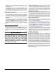
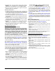
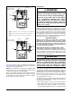
Figure 10. Vertical Vent Termination
Combustion Air
Exhaust Vent
12” Above Maximum
Expected Snow Level
(Both pipes)
Elbows on the combustion air
inlet must be positioned pointing
away from the exhaust vent.
8" Min.
36" Max.
Plumbing Vent Roof Boot
(Both Pipes)
• If venting horizontally, a side wall vent kit is available
according to the pipe diameter size of the installation. For
2 inch pipe use side wall vent kit #904617, and for 3 inch
pipe use kit #904347. Please follow the instructions
provided with the kit.
• Concentric vent kits are available for both 2” and 3”
applications. Each size has one that meets UL 1738 and
one that meets ULC S636. Refer to the technical sales
literature for kit numbers.
• When the vent pipe must exit an exterior wall close to the
grade or expected snow level where it is not possible to
obtain clearances shown in
Figure 7 (page 10), a riser may
be provided as shown in
Figure 9 (page 10). Insulation
is required to prevent freezing of this section of pipe. See
Table 2 for vent freezing protection.
Outdoor Terminations - Vertical Venting
Termination spacing requirements from the roof and from
each other are shown in
Figure 10. The roof penetration must
be properly flashed and waterproofed with a plumbing roof
boot or equivalent flashing. Vent and combustion air piping
may be installed in an existing chimney which is not in use
provided that:
• Both the exhaust vent and air intake run the length of the
chimney.
• The top of the chimney is sealed and weatherproofed.
• The termination clearances shown in
Figure 10 are
maintained.
• No other gas fired or fuel-burning equipment is vented
through the chimney.
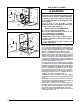
Vent Freezing Protection
CAUTION:
When the vent pipe is exposed to temperatures
below freezing (i.e., when it passes through
unheated spaces, chimneys, etc.) the pipe
must be insulated with 1/2 inch thick sponge
rubber insulation, Armaflex-type insulation or
equivalent. Insulating pipe is important to avoid
condensate icing.
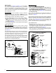
• Table 2 lists the maximum length of flue pipe that can travel
through an unconditioned space or an exterior space. The
total vent length must not exceed the lengths noted in
Table
1 (page 9)
. For Canadian installations, please refer to
the Canadian Installation Code (CAN/CGA-B149.1) and/
or local codes.
• For extremely cold climates or for conditions of short
furnace cycles (i.e. set back thermostat conditions) the last
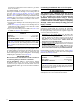
WINTER DESIGN
TEMPERATURE
MAXIMUM FLUE PIPE LENGTH (FEET)
IN UNCONDITIONED & EXTERIOR SPACES
WITHOUT INSULATION WITH INSULATION*
20 45 70
0 20 70
-20 10 60
*NOTE: Insulation thickness greater than 3/8 inch, based on an
R value of 3.5 (ft x F x hr) / (BTU x in.)
Table 2. Vent Protection