
J951X Installation Manual


21
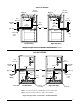
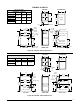
Figure 23. Typical Gas Connections - Upflow Models
Elbow
J951X*U SERIES
See
Note “B”
See
Note “B”
Right Side Entry
Left Side Entry
See
Note “A”
See
Note “A”
Burner
Assembly
Burner
Assembly
Manifold
Manifold
Drip Leg
Dr
ip Leg
Shut-Off
Valve
Shut-Off
Valve
Gas
Valve
Gas
Valve
Elbow
Pipe
Nipple
Pipe
Nipple
Plug
Ground
Joint
Union
Ground
Joint
Union
NOTE A: Consult local codes for Shut-Off Valve location requirements
NOTE B: Inducer assembly omitted for clarity of pipe installatio
Figure 24. Typical Gas Connections - Downflow Models
Ground
Joint
Union
J951X*D SERIES
Right Side Entry
Left Side Entry
See
Note “B”
See
Note “B”
Manifold
See
Note “A”
See
Note “A”
NOTE A: Consult local codes for Shut-Off Valve location requirements
NOTE B: Inducer assembly omitted for clarity of pipe installatio
Burner
Assembly
Manifold
Dr
ip Leg
Drip Le
g
Shut-Off
Valve
Shut-Off
Valve
Gas
Valve
Gas
Valve
Pipe
Nipple
Pipe
Nipple
Plug
Ground
Joint
Union
Elbow
Elbow
Ground
Joint
Union