
J801X Installation Manual

18
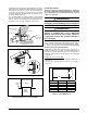
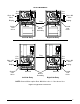
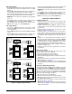
Figure 14. Line Voltage Field Wiring
Field Supplied
Disconnect within
Sight of Furnace
Field Supplied
Panel Connector
Field Supplied
Fused Service
Panel
Black (Hot)
White (Neutral)
Green or Bare (Ground)
Field Line Voltage Wiring
Factory Line Voltage Wiring
Ground
Ground
Junction Box (may be int. or ext. to the furnace). These connections can be made in the field supplied disconnect at the furnac
e.
NOTE: Connections made within the furnace burner compartment do not require a junction box.
Ground
Black
White
Black
White
Black
White
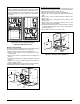
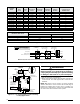
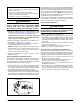
RCYGW
STATUS
FLAME
GREEN
RED
180
COOL
HEAT
120
90
60
YELLOW
BLOWER
OFF
DELAY
LOW
ML
MH
HIGH
EAC
L1
XFMR
HUM
COM
SPEED
SELECT
3 AMP
FUSE
24V
5
NEUTRALS
ROOM
THERMOSTAT
A/C
CONDENSING
UNIT
CONDENSING UNIT
CONTROL BOX
EXPANSION PORT
(MOT
OR CONNECTION)
FIELD WIRING
LOW VOLTAGE
CONNECTION
R
C
Y
G
W
NOTE: The “Y” terminal
on the control board
must be connected to
the thermostat for
proper cooling mode
operation.
Connect
R & W
For
Heating
Only
2
ELECTRONIC AIR CLEANER
MOTOR SPEED TAPS
(NOT USED)
HUMIDIFIER TAP
NEUTRAL LEADS
6 3
4
1
7
8
9
5
2
63
4
1
FAN
MH
L
H
ML
JUMPER PIN
SETUP
Figure 15. Low Voltage Field, Four-wire Heating/
Cooling Applications
WARNING:
When servicing either twinned furnace, power
must be turned off on both furnaces. Failure to
comply may result in improper operation leading
to damage to the furnaces or personal injury!
1. Turn off all power to both furnaces.
2. Attach a wire between the two twin terminals on the blower
control boards. Use field supplied wire and 3/16” wire
terminals.
NOTE: One furnace can be used for one stage of heating
and the other furnace can be used for the second stage of
heating. The installer also has the choice of running one
furnace only or both furnaces. In both cases the blowers will
run at the same time and at the same speeds:
Table 2. Wire Length & Voltage Specifications
FURNACE
MODEL
FURNACE
INPUT
(BTUh)
CABINET
WIDTH
(IN.)
NOMINAL
ELECTRICAL
SUPPLY
MAXIMUM
OPERATING
VOLTAGE
MINIMUM
OPERATING
VOLTAGE
MAXIMUM
FURNACE
AMPERES
MAXIMUM
FUSE OR CIRCUIT
BREAKER AMPS*
J801X045AU 45,000 14 1/4 115-60-1 127 103 6.8 15
J801X054AU 52,000 14 1/4 115-60-1 127 103 6.8 15
J801X072BU 70,000 17 1/2 115-60-1 127 103 9.2 15
J801X072CU 75,000 21 115-60-1 127 103 9.2 15
J801X090BU 90,000 17 1/2 115-60-1 127 103 9.2 15
J801X090CU 85,000 21 115-60-1 127 103 11.9 20
J801X108CU 108,000 21 115-60-1 127 103 11.9 20
J801X126DU 122,000 24 1/2 115-60-1 127 103 11.9 20
J801X054AD 52,000 14 1/4 115-60-1 127 103 6.8 15
J801X072BD 75,000 17 1/2 115-60-1 127 103 9.2 15
J801X090BD 90,000 17 1/2 115-60-1 127 103 9.2 15
J801X108CD 108,000 21 115-60-1 127 103 11.9 20
J801X126DD 126,000 24 1/2 115-60-1 127 103 11.9 20
* Time-delay fuses or circuit breakers are required.
THERMOSTAT WIRE GAUGE
RECOMMENDED THERMOSTAT WIRE LENGTH
2 - WIRE - HEATING 4 OR 5 WIRE - COOLING
24 55 ft. 25 ft.
22 90 ft. 45 ft.
20 140 ft. 70 ft.
18 225 ft. 110 ft.