
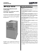
J801X Technical Specs


5
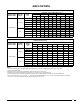
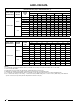
HEATING AIRFLOW (CFM) & TEMPERATURE RISE (°F)
MODEL NAME/
HEATING INPUT
RETURN
AIR VIA:
MOTOR
SPEED
TAP
EXTERNAL STATIC PRESSURE (IN. W.C.)
0.1 0.2 0.3 0.4 0.5
CFM RISE CFM RISE CFM RISE CFM RISE CFM RISE
055AU3LAAA
Bottom
5 - High *
4 - Med-High
3 - Med-Low ** 880 46 845 48 810 50 770 53 735 55
2 - Alternate 705 58 650 63 610 570 530
1 - Low *** 640 64 600 555 510 470
Side
5 - High *
4 - Med-High
3 - Med-Low ** 875 47 830 49 795 51 750 54 715 57
2 - Alternate 685 59 650 63 595 555 515
1 - Low *** 640 64 585 540 500 460
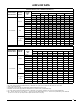
COOLING AIRFLOW (CFM)
MODEL NAME/
HEATING INPUT
RETURN
AIR VIA:
MOTOR
SPEED
TAP
EXTERNAL STATIC PRESSURE (IN. W.C.)
0.1 0.2 0.3 0.4 0.5 0.6 0.7 0.8
CFM CFM CFM CFM CFM CFM CFM CFM
055AU3LAAA
Bottom
5 - High * 1,180 1,140 1,110 1,080 1,045 1,015 985 955
4 - Med-High 920 880 850 810 775 740 700 665
3 - Med-Low ** 880 845 810 770 735 700 665 630
2 - Alternate 705 650 610 570 530 480 440 400
1 - Low *** 640 600 555 510 470 430 390 340
Side
5 - High * 1,160 1,125 1,095 1,065 1,040 1,010 975 945
4 - Med-High 905 860 827 790 755 717 683 639
3 - Med-Low ** 875 830 793 752 715 684 642 606
2 - Alternate 685 650 595 555 515 471 424 376
1 - Low *** 640 585 540 500 460 415
NOTES:
1. To comply with government mandated efficiency standards, two openings are required for airflows above 1,600 CFM.
2. Data is shown without filter.
3. Temperature rises in the table are approximate. Actual temperature rises may vary.
4. Individual cells shaded in gray indicate a temperature rise outside of the recommended range.
5. To comply with government mandated efficiency standards, speed settings shaded in gray are not allowed in HEAT mode.
6. The "*" denotes the factory COOL setting, "**" denotes the factory HEAT setting, and "***" denotes factory FAN setting. If the Alternate
speed is to be used, the speed tap must be adjusted at the blower motor plug.
AIRFLOW DATA