
J801X Installation Manual

18
4. Turn the gas control switch to the OFF position.
5. Remove the 2 screws securing the combustion air orifice
plate to the air/fuel mixing tube (if needed to access the
ignitor/flame sensor assembly cover on smaller models).
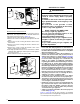
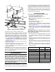
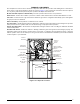
6. Remove 8 screws from perimeter of access cover plate.
7. Lift the assembly and bracket straight up out of the burner
box and off the HX panel. NOTE: Use of a flat blade
screwdriver between assembly bracket and top of burner
mounting bracket to help leverage bracket off may be
required. See Figure 16.
8. Clean the flame sensor using steel wool being careful not
to damage the igniter.
9. Replace old gasket with new gasket ensuring correct
orientation, with adhesive side to the bracket.
10. Replace igniter/flame sense assembly in reverse order
they were removed.
Vent System - Check the vent pipe and/or chimney for
corrosion or debris. Any corroded section of vent pipe must be
replaced, and any obstruction or blockage must be removed
prior to operating the furnace.
WARNING:
Holes in the vent pipe or heat exchanger can
cause combustion products to enter the home.
Replace the vent pipe or heat exchanger if leaks
are found. Failure to prevent the circulation of
combustion products into the living space can
create potentially hazardous conditions including
carbon monoxide poisoning that could result in
personal injury or death.
Heat Exchanger & Burner Maintenance - The furnace
should operate for many years without soot buildup in the
flue passageways, however, the flue and vent system should
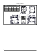
DIAGNOSTIC DESCRIPTION GREEN LED RED LED
Control Fault (No Power) Off Off
L1/Neutral Polarity Fault Flash Flash
1 Hour Lockout Alternating Flash
Normal Operation On On
Pressure Switch Closed Fault On Flash
Pressure Switch Open Fault Flash On
Open Limit Switch Fault Flash Off
DIAGNOSTIC DESCRIPTION YELLOW LED
Low Flame Sensor Signal Continuous Flash
Flame Present On
Table 2. Control Board Fault Conditions
be inspected and cleaned (if required) by a qualified service
technician annually to ensure continued safe operation. Pay
attention to any deterioration from corrosion or other sources.
Lubrication - The bearings in the blower motor and inducer
blower used in these furnaces are pre-lubricated and sealed
by the manufacturer. No further oiling of the bearings is
required for the life of the motor.
TROUBLESHOOTING
If the furnace fails to operate check the following:
• Is the thermostat operating properly?
• Is the blower compartment doors in place?
• Is the furnace disconnect closed?
• Has the circuit breaker tripped or the control board fuse
burned open?
• Is the gas turned on?
• Are any manual reset switches open?
• Is the filter dirty or plugged?
• Is the flame sensor coated? (Remove and clean with steel
wool. New gasket is required) See Cleaning of Flame
Sensor section page 17.
• Are all the LED’s on the furnace control board constantly
ON? If not, refer to Table 2 or the wiring diagrams (Figure
19, (page 24)) and Figure 20, (page 25) to determine
fault condition.
IMPORTANT NOTE: The furnace will lock out after 5
failed attempts for ignition and will try again every hour
if the call for heat remains.
• If the inducer blower is operating and items above have
been verified, check the limit switch circuit and reset if
necessary. See Figure 17, (page 19) for component
location.
• If the furnace operates when the limit switch circuit is reset,
contact a qualified service technician to identify and repair
the problem.
• If the furnace still doesn’t operate, check the flame roll-out
switch and reset if necessary. See Figure 17 for component
location.
• If the furnace operates when the flame rollout switch is
reset, contact a qualified service technician to identify and
repair the problem.
Figure 16. Ignitor Flame Sensor Bracket
Access Cove
r
Perimeter
Screws (x8)