
J801X Installation Manual

17
5. The control energizes the igniter output for a 30 second
warm-up period.
6. The control energizes the main gas valve for 3 seconds.
7. If the flame is proved after igniting the gas, the control de-
energizes the igniter. The gas valve and inducer remain
energized. The control goes to blower on delay.
8. If flame is present, the control energizes the blower on
the selected HEAT speed 30 seconds after the gas valve
opened. The gas valve remains energized while the inducer
ramps to Max. RPM over a programmed time period.
9. When the thermostat demand for heat is satisfied, the
control de-energizes the gas valve. The inducer output
remains on for a 30 second post-purge period.
10. Blower off timing of 60, 90, 120, & 180 seconds (depending
on the movable jumper setting) begins when the thermostat
is satisfied. See Figure 14 (page 16). The control will
operate at the selected HEAT speed of 60 seconds, then
change to FAN speed for the remaining off delay time. If
the blower off delay jumper is not present, the fan should
still operate for 120 seconds at the selected HEAT speed.
The indoor blower motor is de-energized after a blower
off delay as selected by the movable jumper.
Cooling Cycle
1. The thermostat calls for cooling by energizing the Y & G
terminal with 24VAC.
2. The control energizes the blower in the cooling speed and
sends 24VAC to the contactor in the condensing unit.
3. When the thermostat removes the call for cooling, the
contactor in the outdoor condensing unit is de-energized
and the control continues to run the fan for a period of 60
seconds.
Fan Mode
• When the thermostat energizes the G terminal for
continuous fan (without calling for heat or cooling), the
indoor fan is energized on the selected FAN speed. See
Figure 13, (page 14). The control defaults to MEDIUM
HIGH if the movable jumper is not attached.
• If a call for cooling occurs during continuous fan, the blower
will switch over to the selected COOL speed.
• If the W terminal receives a call for heat during continuous
fan, the blower will de-energize and reset to delayed ON
timing.
• A call for fan is ignored while in lockout.
MAINTENANCE
WARNING:
ELECTRICAL SHOCK, FIRE OR
EXPLOSION HAZARD
Failure to follow safety warnings exactly could
result in serious injury, death or property
damage.
Improper servicing could result in dangerous
operation, serious injury, death or property
damage.
• Before servicing, disconnect all electrical
power to furnace.
• When servicing controls, label all wires prior
to disconnecting. Reconnect wires correctly.
• Verify proper operation after servicing.
Proper maintenance is most important to achieve the best
performance from a furnace. Follow these instructions for
years of safe, trouble free operation.
• These maintenance instructions are primarily intended
to assist qualified technicians experienced in the proper
maintenance and operation of this appliance.
• Always reinstall the doors on the furnace after servicing or
cleaning/changing the filters. Do not operate the furnace
without all doors and covers in place.
• Verify the thermostat is properly installed and is not being
affected by drafts or heat from lamps or other appliances.
• To achieve the best performance and minimize equipment
failure it is recommended that a yearly maintenance
checkup be performed. At a minimum, this check should
include the following items:
Air Filter - An air filter is not supplied with the furnace as
shipped from the factory. The installer must provide a high
velocity filter that is appropriately sized to the return air duct
opening or external filter rack.
WARNING:
Never operate the furnace without a filter in place.
Dust and lint can build up on internal components,
resulting in loss of efficiency, equipment damage,
and possible fire.
It is recommended that filter(s) be 1” or 2” thick and be cleaned
or replaced monthly. New or newly renovated homes may
require more frequent changing until the construction dust
has minimized.
Filters designed to remove smaller particles such as pollen,
may require additional maintenance. Filters for side return
and bottom return applications are available from most local
distributors.
Blower Compartment - Dirt and lint can create excessive
loads on the motor resulting in higher than normal operating
temperatures and shortened service life. It is recommended
that the blower compartment be cleaned of dirt or lint that
may have accumulated in the compartment or on the blower
and motor as part of the annual inspection.
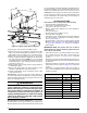
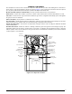
Cleaning of Flame Sensor - If the flame sensor is suspect
for Loss of Flame fault code, the sensor can be cleaned
to see if that remedies the issue. Follow steps 1 - 10. See
Figure 17, (page 19) for component location.
CAUTION:
Due to igniter/flame sensor assembly location, a
new gasket should be on hand before servicing
this part. One new gasket is provided in the
furnace extra parts package. Failure to re-seal
the assembly after service can result in abnormal
furnace operation.
1. Shut off gas supply to the furnace at the meter or at a
manual valve in the supply piping.
2. Turn off all power to the furnace and set the thermostat
to its lowest setting.
3. Remove the louvered door from the furnace.