
J801X Installation Manual

15
warm air registers or electrical appliances. Refer to the
thermostat manufacturer’s instruction sheet for detailed
mounting information.
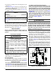
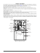
• The six pin terminal marked “Expansion Port” (Figure 13,
(page 14)) is not used in the single stage furnace as
shipped from the factory. It is used for the furnace control
board to communicate to a fixed speed or variable speed
high efficiency motor that may be optionally installed. Please
contact your distributor for the proper upgrade motor kit.
Heat Anticipator
Set the heat anticipator according to the instructions supplied
by the thermostat manufacturer. To determine the heat
anticipator setting:
1. Add the current draw of the system components; or
2. Measure the current flow on the thermostat R-W circuit
after the circulating blower motor has started.
START-UP & ADJUSTMENTS
Pre-Start Check List
√ Verify the polarity of the connections are correct, the line
voltage power leads are securely connected and the furnace
is properly grounded.
√ Verify the thermostat wires (R, W, Y, & G) are securely
connected to the correct leads on the terminal strip of the
circuit board.
√ Verify the jumper setting (for fan speed) on the control
board. See Figure 13, (page 14).
√ Verify the gas line service pressure does not exceed 10.0
inches of W.C., and is not less than 4.5 inches W.C. for
natural gas.
Table 1. Electrical Specifications
FURNACE
MODEL
*SA-
FURNACE
INPUT
(BTUH)
CABINET
WIDTH
(IN.)
NOMINAL
ELECTRICAL
SUPPLY
MAXIMUM
OPERATING
VOLTAGE
MINIMUM
OPERATING
VOLTAGE (†)
MAXIMUM
FURNACE
AMPERES
MINIMUM
CIRCUIT
AMPACITY
(MCA)
MAXIMUM
FUSE OR CIRCUIT
BREAKER AMPS*
J801X055A 55,000 14 1/4 120-60-1 132 108 7.2 8.73 15
J801X070B 70,000 17 1/2 120-60-1 132 108 9.5 11.60 20
J801X100C 100,000 21 120-60-1 132 108 12.1 14.85 25
* Time-delay fuses or HACR rated circuit breakers are reccomended. † At 108V operating voltage, the unit may not operate properly.
THERMOSTAT WIRE GAUGE
RECOMMENDED THERMOSTAT WIRE LENGTH
2 - WIRE - HEATING 4 OR 5 WIRE - COOLING
24 55 ft. 25 ft.
22 90 ft. 45 ft.
20 140 ft. 70 ft.
18 225 ft. 110 ft.
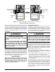
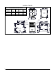
Field Supplied
Disconnect within
Sight of Furnace
Field Supplied
Panel Connector
Field Supplied
Fused Service
Panel
Black (Hot)
White (Neutral)
Green or Bare (Ground)
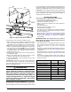
Field Line Voltage Wiring
Factory Line Voltage Wiring
Ground
Ground
Junction Box (may be int. or ext. to the furnace). These connections can be made in the field supplied disconnect at the furnac
e.
NOTE: Connections made within the furnace burner compartment do not require a junction box.
Ground
Black
White
Black
White
Black
White
Figure 14. Line Voltage Field Wiring
√ Verify the roll-out manual reset switch is closed. If
necessary, press the red button to reset a switch. DO NOT
install a jumper wire across a switch to defeat its function.
If a switch reopens on startup, DO NOT reset the switch
without identifying and correcting the fault condition.
√ Verify the blower door is in place, closing the door switch
in the line voltage circuit.
√ Verify the gas line has been purged and all connections
are leak free.
Start-up Procedures
Do not perform these steps until all of the checks in the
previous steps have been completed:
1. Set the thermostat to the lowest setting.
2. Turn off all electrical power to the furnace.
3. Follow the Operating Instructions on the label attached to
the furnace.
4. Set the thermostat above room temperature and verify the
Operating Sequence (page 16).
5. After 5 minutes of operation, set the thermostat below
room temperature and verify steps 9 - 10 of the Operating
Sequence.
Verifying & Adjusting Input Rate
The input rate must be verified for each installation to prevent
over-firing of the furnace. NOTE: The input rate must not
exceed the rate shown on the furnace rating plate. At altitudes
above 2,000 feet, it must not exceed that on the rating plate
less 4% for each 1,000 feet. To determine the exact input
rate, perform the following procedures:
1. Shut off all other gas fired appliances.
2. Start the furnace and run it for at least 3 minutes.
3. Measure the time (in seconds) required for the gas meter
to complete one revolution.