
J801X Installation Manual

14
1. Consult the local utility for the local heating value at your
installation site.
2. From Table 8, (page 27), find your local heating value as
supplied by the utility company. Follow down the column
and stop at your altitude level.
3. If your sea level heating value is HIGH, use Table 9 or if
it’s LOW, use Table 10.
EXAMPLE
Elevation: ......................................................5,000 feet
Type of Gas: .............................................. Natural Gas
Local Heating Value of Gas: .................................. 750
From Table 8, find 750 and follow down the column, stop
at the 5,000 feet row. The heating value listed is LOW.
Table 10 will be used to determine orifice size and manifold
pressure
After changing the regulator pressure or the orifices, it is
required that you measure the gas input rate. This may be
accomplished in the usual way, by clocking the gas meter
and using the local gas heating value. See Verifying and
Adjusting the Input Rate section (page 15).
IMPORTANT NOTE:
Observe operation of the furnace to make sure there are
no abnormal noises at ignition or during steady state
operation.
ELECTRICAL WIRING
WARNING:
ELECTRICAL SHOCK, FIRE OR
EXPLOSION HAZARD
Failure to follow safety warnings exactly could
result in serious injury, death or property
damage.
Improper servicing could result in dangerous
operation, serious injury, death or property
damage.
• Before servicing, disconnect all electrical
power to furnace.
• When servicing controls, label all wires prior
to disconnecting. Reconnect wires correctly.
• Verify proper operation after servicing.
• Electrical connections must be in compliance with all
applicable local codes and the current revision of the
National Electric Code (ANSI/NFPA 70).
Line Voltage Wiring
It is required that the line voltage (120 VAC) to the furnace
be supplied from a dedicated branch circuit containing the
correct fuse or circuit breaker for the furnace. See Table 1.
IMPORTANT NOTES:
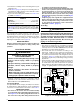
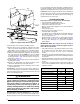
• An electrical disconnect must be installed readily
accessible from and located within sight of the furnace.
See Figure 14 or the wiring diagram label inside of
the control door. Any other wiring methods must be
acceptable to authority having jurisdiction.
• Proper line voltage polarity must be maintained in order
for the control system to operate correctly. Verify the
incoming neutral line is connected to the white wire
and the incoming “hot” line is connected to the black
wire. The furnace will not operate unless the polarity
and ground are properly connected as shown in Figure
14, (page 15).
• If replacing any of the original wires supplied with the
furnace, the replacement wire must be copper wiring
and have a temperature rating of at least 105° F (40°
C). For electrical specifications, refer to the furnace
nameplate or Table 1, (page 15).
Grounding
WARNING:
To minimize personal injury, the furnace cabinet
must have an uninterrupted or unbroken electrical
ground. The controls used in this furnace require
an earth ground to operate properly. Acceptable
methods include electrical wire or conduit
approved for ground service. Do not use gas
piping as an electrical ground!
Thermostat / Low Voltage Connections
• The furnace is designed to be controlled by a 24 VAC
thermostat. The thermostat’s wiring must comply with the
current provisions of the NEC (ANSI/NFPA 70) and with
applicable local codes having jurisdiction.
• The thermostat must be installed according to the
instructions supplied by the thermostat manufacturer.
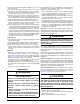
Low voltage connections (24 VAC) from the thermostat
are wired to the terminal strip on the integrated control in
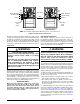
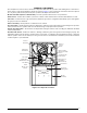
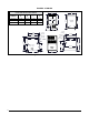
the furnace. Figure 13 contains the proper connections
for heating only (two-wire) and heating/cooling (four-wire)
applications.
• The thermostat should be mounted about 5 feet above the
floor on an inside wall. DO NOT install the thermostat on
an outside wall or any other location where its operation
may be adversely affected by radiant heat from fireplaces,
sunlight, or lighting fixtures, and convective heat from
Figure 13. Low Voltage Connections
RCYGW
STATUS
FLAME
GREEN
RED
180
COOL
HEAT
120
90
60
YELLOW
BLOWER
OFF
DELAY
LOW
ML
MH
HIGH
EAC
L1
XFMR
HUM
COM
SPEED
SELECT
3 AMP
FUSE
24V
5
NEUTRALS
ROOM
THERMOSTAT
A/C
CONDENSING
UNIT
CONDENSING UNIT
CONTROL BOX
FIELD WIRING
LOW VOLTAGE
CONNECTION
R
C
Y
G
W
NOTE: The “Y” terminal
on the control board must
be connected to the
thermostat for proper
cooling mode operation.
Connect
R & W
For
Heating
Only
2
ELECTRONIC AIR CLEANER
(120V Output, 1 amp max)
MOTOR
SPEED
TAPS
HUMIDIFIER TA P
(120V Output, 1 amp max)
NEUTRAL LEADS
6 3
4
1
7
8
9
5
2
63
4
1
FAN
MH
L
H
ML
JUMPER PIN
SETUP
Expansion Port
(Motor Connection)
(Not Used)
120
60
180
90