
J801X Installation Manual

13
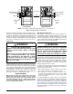
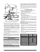
The furnace may be installed for either left or right side gas
entry by removing the 1/2” plug from the tee and replacing it to
the side not used. When connecting the gas supply, provide
clearance between the gas supply line and the entry hole in
the furnace casing to avoid unwanted noise and/or damage
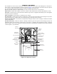
to the furnace. Typical gas hookups are shown in Figure 12.
Leak Check
WARNING:
FIRE OR EXPLOSION HAZARD
Failure to follow safety warnings exactly could
result in serious injury, death or property
damage.
Never test for gas leaks with an open flame.
Use a commercially available soap solution
made specifically for the detection of leaks
to check all connections. A fire or explosion
may result causing property damage, personal
injury or loss of life.
After the gas piping to the furnace is complete, all connections
must be tested for gas leaks. This includes pipe connections
at the main gas valve, emergency shutoff valve and flexible
gas connectors (if applicable). The soap and water solution
can be applied on each joint or union using a small paintbrush.
If any bubbling is observed, the connection is not sealed
adequately and must be retightened. Repeat the tightening
and soap check process until bubbling ceases.
IMPORTANT NOTE:
When pressure testing gas supply lines at pressures
greater than 1/2 psig (14 inch W.C.), the gas supply
piping system must be disconnected from the furnace
to prevent damage to the gas control valve. If the test
pressure is less than or equal to 1/2 psig (14 inch W.C.),
close the manual shut-off valve.
High Altitude Application
High altitude conversion with this furnace depends on
the installation altitude and the heating value of the gas.
Installation of this furnace at altitudes above 2,000 feet shall
be in accordance with local codes, or in the absence of local
codes, the National Fuel Gas Code, ANSI Z223.1/NFPA 54.
Please consult your local code authority.
WARNING:
The reduction of input rating necessary for high
altitude installation may only be accomplished
with factory supplied orifices. Do not attempt to
drill out orifices in the field. Improperly drilled
orifices may cause fire, explosion, carbon
monoxide poisoning, personal injury or death.
The furnaces are shipped from the factory with orifices and
gas regulator settings for natural gas operation at sea level
altitudes. At 2,000 feet, the NFGC requires that this appliance
be derated 4% for each 1,000 feet of altitude. For example,
at 2,000 feet the input needs to be reduced 8%, at 3,000
feet (12%), etc. This deration is in reference to the input rate
and gas heating value at sea level.
To derate the furnace requires knowing the heating value of
the gas at the installation site. Heating values at particular
job sites vary for two reasons:
1. The chemical mixture of the gas varies across regions
and is expressed as the “sea level heating value”.
2. The heating value varies by altitude. For this reason,
especially in high altitude areas, the local gas utility
specifies the heating value at the residence’s gas meter
as the “local value”.
For added flexibility, two tables have been provided for
natural gas installations with HIGH or LOW heating values
at sea level. Table 9 & Table 10, (page 27) contain the
orifice sizes and manifold pressure to use at various altitudes.
Table 9 (High) is for natural gas installations with a heating
value of more than 1,000 Btu per cubic foot and Table 10
(Low) is for less than 1,000 Btu per cubic foot. To determine
which table to use:
Figure 12. Typical Gas Connections
Right Side Entry
Left Side Entry
Shut - Off
Valve
Dripleg
Ground
Joint
Union
Plug
See
Note
See
Note
Shut - Off Valv
e
Dripleg
Gas Valve
Ground
Joint
Union
NOTE: Some utilities require Shut- Off Valve to be 4 - 5 feet above floor.
1/8” NPT Plug
1/8” NPT Plug